KVS Splitter and KVS Splicer
Goal
To make the KVS Splitter and KVS Splicer in order to dissemble and assemble a VGA signal.
You will also learn
To make the KVS Splitter and KVS Splicer in order to dissemble and assemble a VGA signal.
You will also learn
- How a VGA signal works, and why it's easy to use
- How to use sockets, breadboards and resistors
- The KVS color coding
- How to shift colors in a VGA signal
Try this at your own risk!
I'm sharing these documents in the spirit of DIY and creative commons. It's basically the tutorial I wish I had had when I became interested in making video synthesis. I am, however, not an authorized electrician or engineer, so if you decide trying these things you do so at your own risk and take full responsibility of any harms done to yourself, the hardware in use, our Earth and the universe in general.
I'm sharing these documents in the spirit of DIY and creative commons. It's basically the tutorial I wish I had had when I became interested in making video synthesis. I am, however, not an authorized electrician or engineer, so if you decide trying these things you do so at your own risk and take full responsibility of any harms done to yourself, the hardware in use, our Earth and the universe in general.
You will need
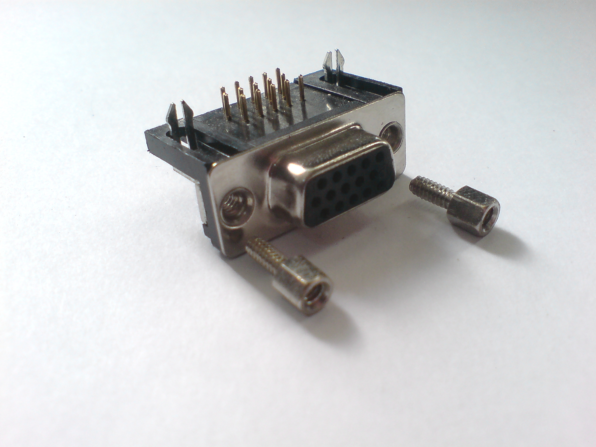
- 2 VGA female sockets (also called 9-pin D-SUB terminals)
- Male-to-female jumper wires (with pin headers)
2 red, 2, green, 2 blue, 2 orange, 2 yellow, [] (xx all in all) - Male-to-male jumper wires (with pin headers)
[] - 3 breadboards*
- 2 plastic boxes for mounting
- 2 VGA cables
- 3 470 ohm resistors (for full experience)
- 2 68 ohm resistors (for full experience)
- Computer with VGA output
- Monitor with VGA input
- Tools to cut and make holes
- [tang til skruerne]
- Tape and two rubber bands
- Pin headers (optional)
- 4 of 3 by 1 headers - 2 of 2 by 1 headers
Step 1: Connecting wires to VGA terminals
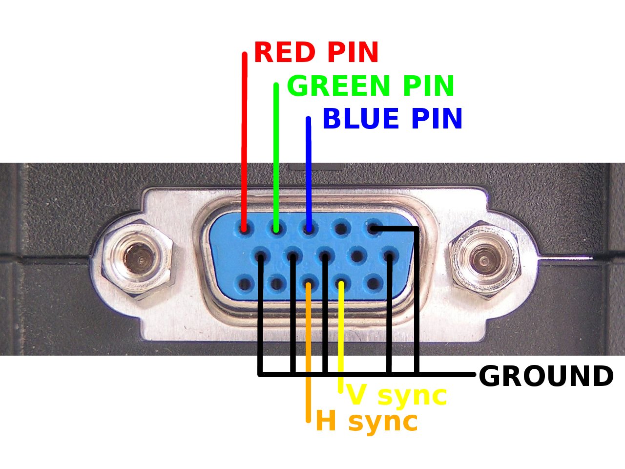
When an image goes through a VGA cable, the signal itself is broken into 15 separate cables. If you look at the ends of a cable, the terminals consists of 15 pins arranged in three rows of five. Each of these contain a different part of the signal that is used to send an image.
Of these 15 pins, five are essential to generate an image. First of all, the three color pins that control the colors through a red, green and blue channel. Second, the two sync pins that controls that the image is synchronized correctly in the horizontal and vertical dimensions. Furthermore, to send an image five ground pins need to be connected to ground (0 volt).
You can identify these pins on the socket through their position like this:
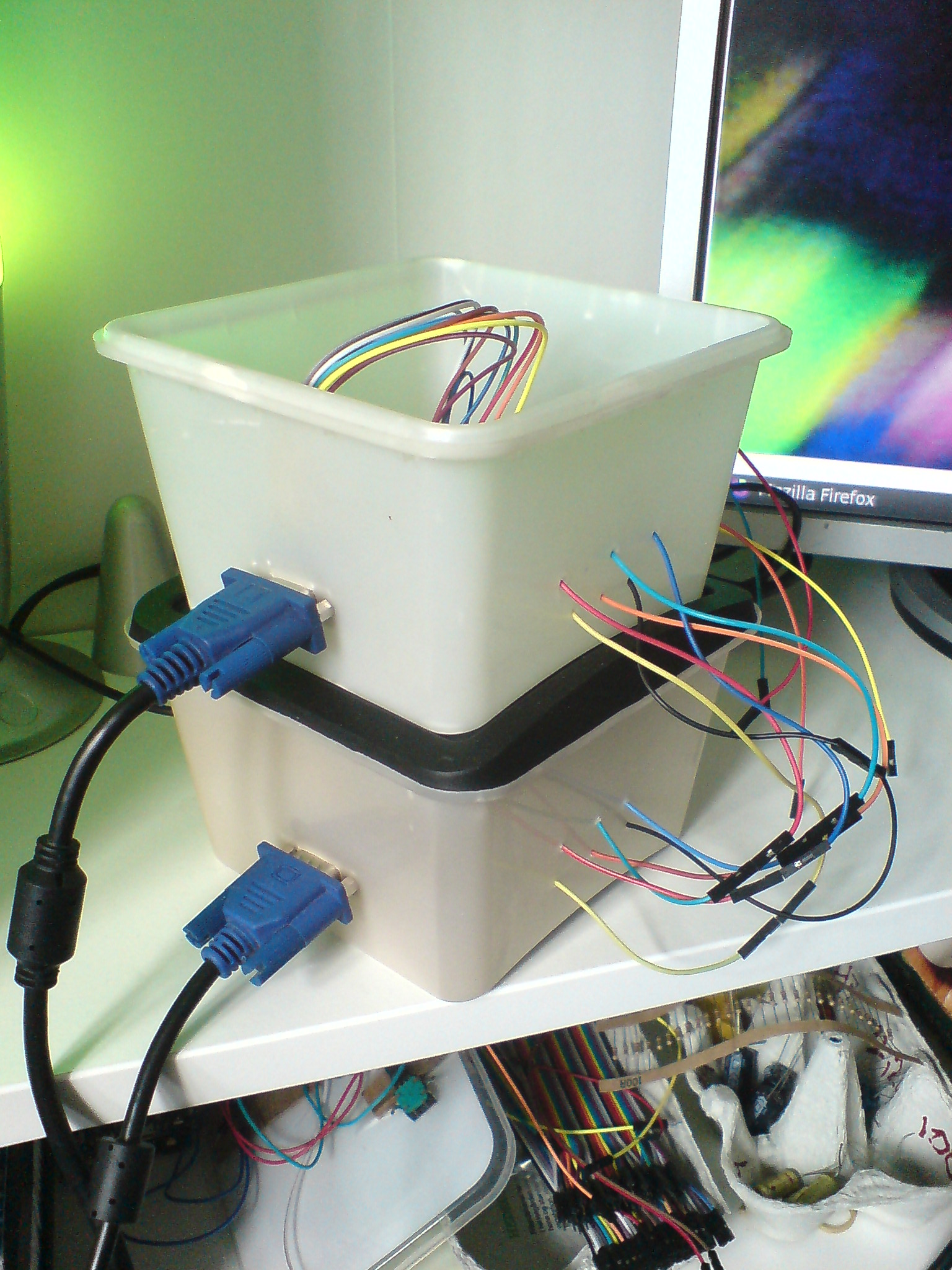
Using two VGA connectors, the pins are converted to print board pins for jumper wires. This way we split and splice each part of the signal individually.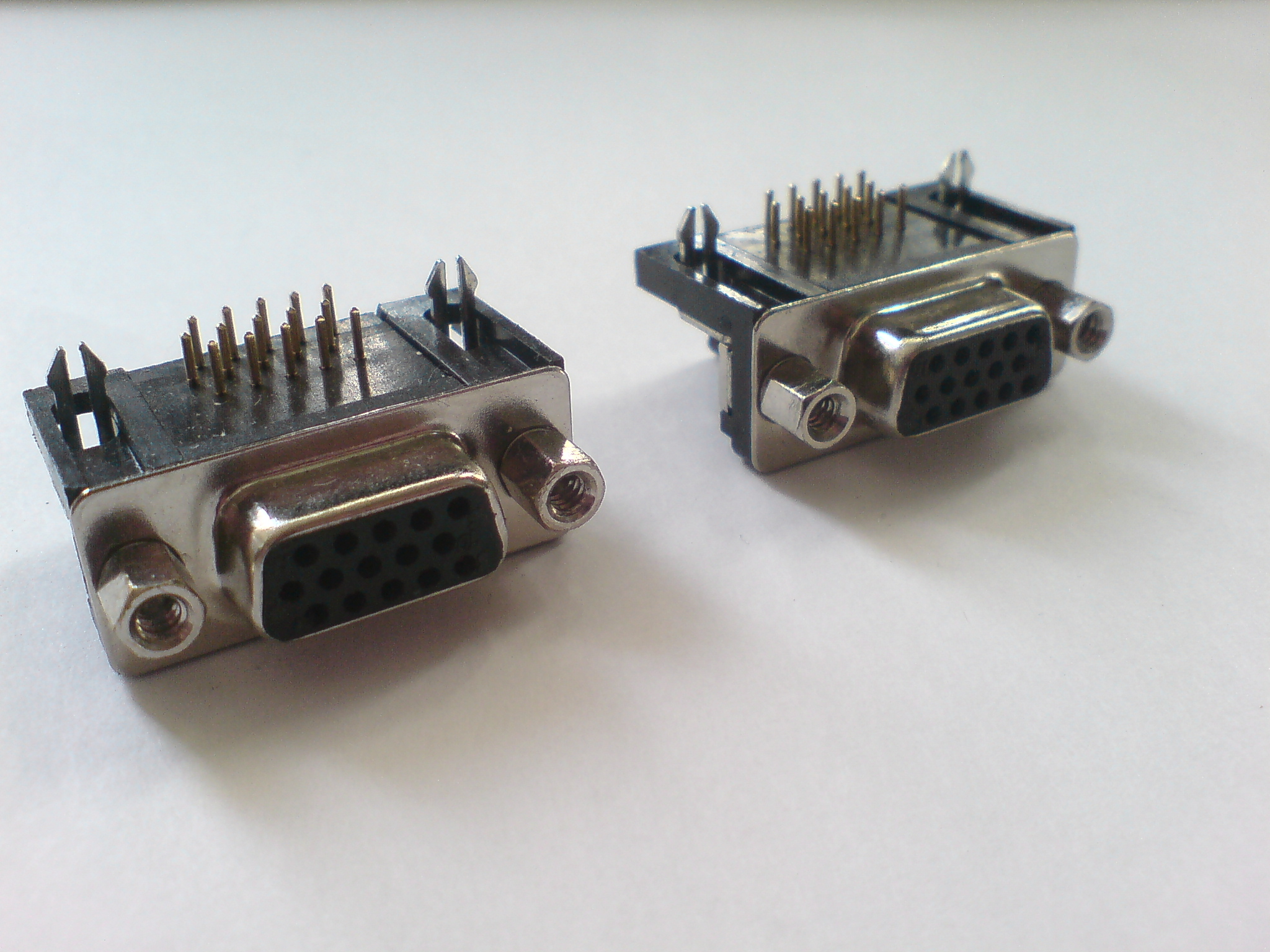
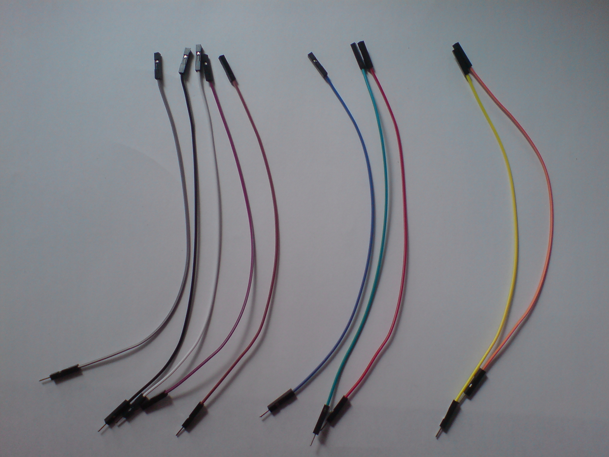
Each socket requires 10 male-to-female wires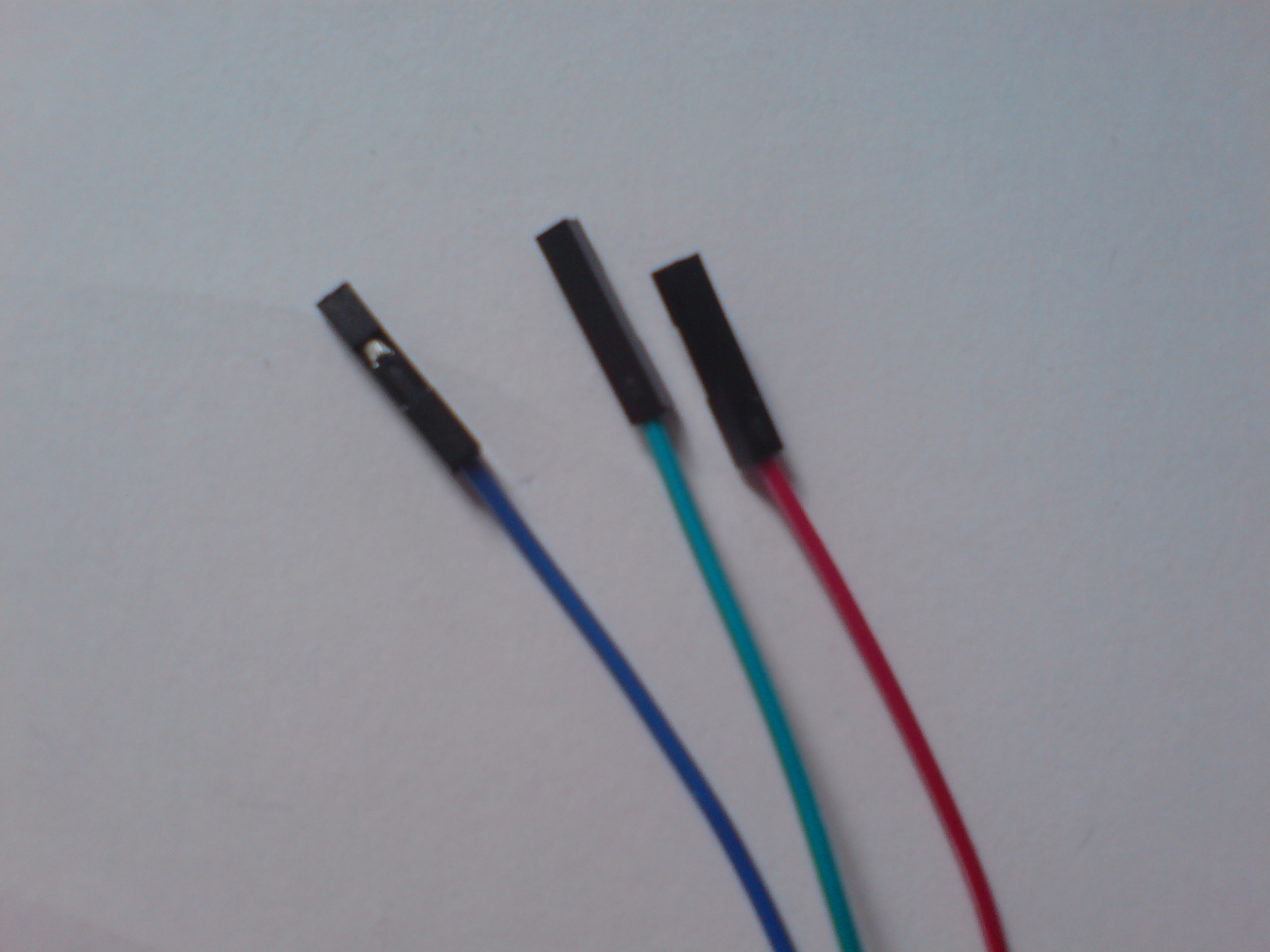
Three color wires (red, green, blue)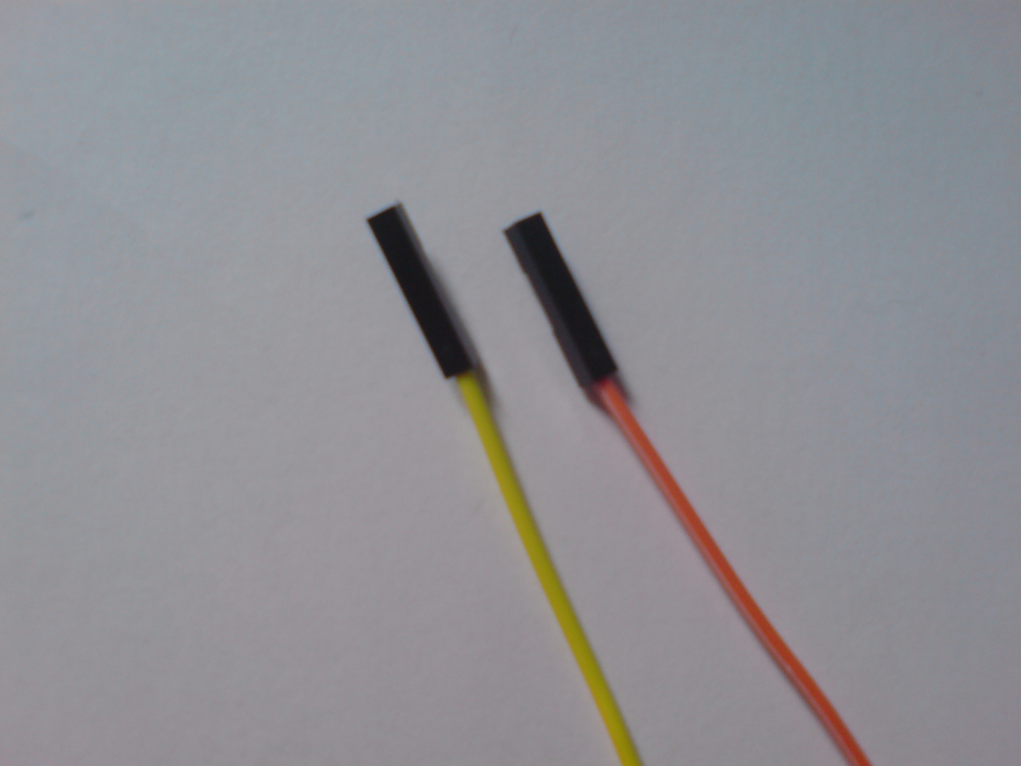
Two sync wires (orange and yellow)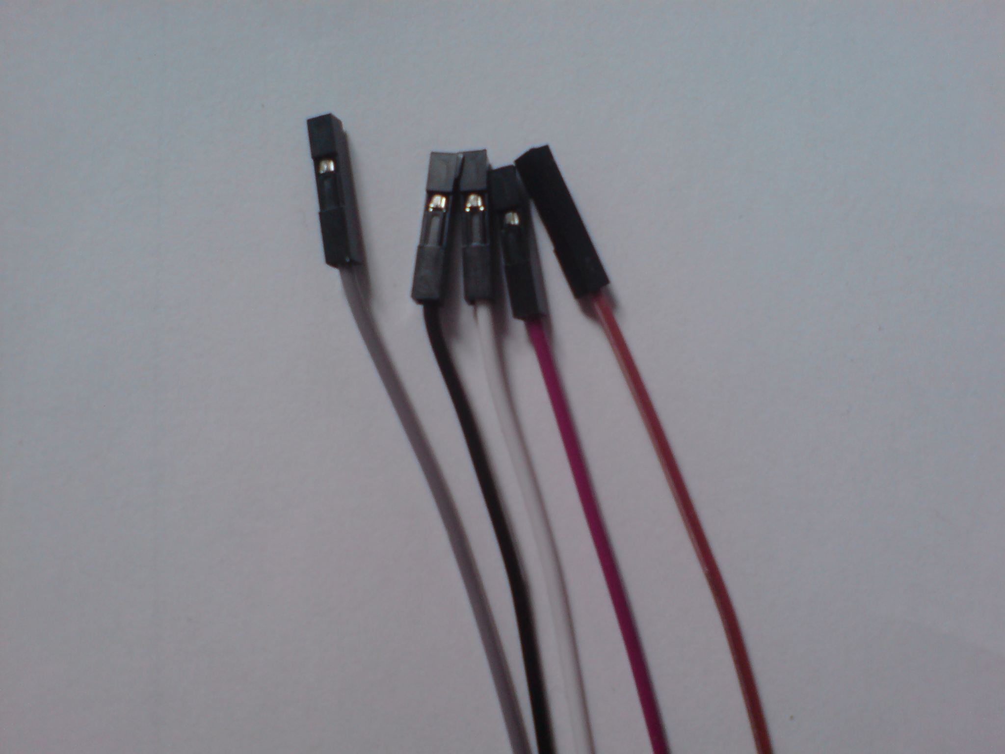
Five ground wires (other colors)
Of these 15 pins, five are essential to generate an image. First of all, the three color pins that control the colors through a red, green and blue channel. Second, the two sync pins that controls that the image is synchronized correctly in the horizontal and vertical dimensions. Furthermore, to send an image five ground pins need to be connected to ground (0 volt).
You can identify these pins on the socket through their position like this:
Using two VGA connectors, the pins are converted to print board pins for jumper wires. This way we split and splice each part of the signal individually.
Each socket requires 10 male-to-female wires
Three color wires (red, green, blue)
Two sync wires (orange and yellow)
Five ground wires (other colors)
| Type | Signal | Wire color | Signal pin | Ground pin |
| Color | Red channel | Red | pin 1 | pin 6 |
| Green channel | GREEN | pin 2 | pin 7 | |
| Blue channel | BLUE | pin 3 | pin 8 | |
| Sync | H sync | ORANGE | pin 13 | pin 5 |
| V sync | YELLOW | pin 14 | pin 10 |
Practical note: Plug directly into socket
If you don't have the VGA sockets, you can alternatively plug the jumper wires directly into the female connectors of computer and monitor. It's a good solution if you just want to try this out, but I don't recommend it for extensive use, because the wires can get very crowded and easily slip out of the connector.
If you don't have the VGA sockets, you can alternatively plug the jumper wires directly into the female connectors of computer and monitor. It's a good solution if you just want to try this out, but I don't recommend it for extensive use, because the wires can get very crowded and easily slip out of the connector.
Practical note: Use tape and rubber bands
Use tape and rubber band to hold the jumper wires in place.
Use tape and rubber band to hold the jumper wires in place.
Theory: Why use VGA signals?
The reason why VGA is such a great signal to manipulate is because the whole signal consists of separate cables. Even though the VGA is often used in connection with a digital output from a graphics card and a digital display (LED, LCD - as opposed to CRT display), the signal itself is sent as analogue electronical waveforms. This means that the electrical signals being sent are easy to manipulate, for example by adding resistance to the circuit, or even to imitate a signal in order to create new, synthetic results.
The reason why VGA is such a great signal to manipulate is because the whole signal consists of separate cables. Even though the VGA is often used in connection with a digital output from a graphics card and a digital display (LED, LCD - as opposed to CRT display), the signal itself is sent as analogue electronical waveforms. This means that the electrical signals being sent are easy to manipulate, for example by adding resistance to the circuit, or even to imitate a signal in order to create new, synthetic results.
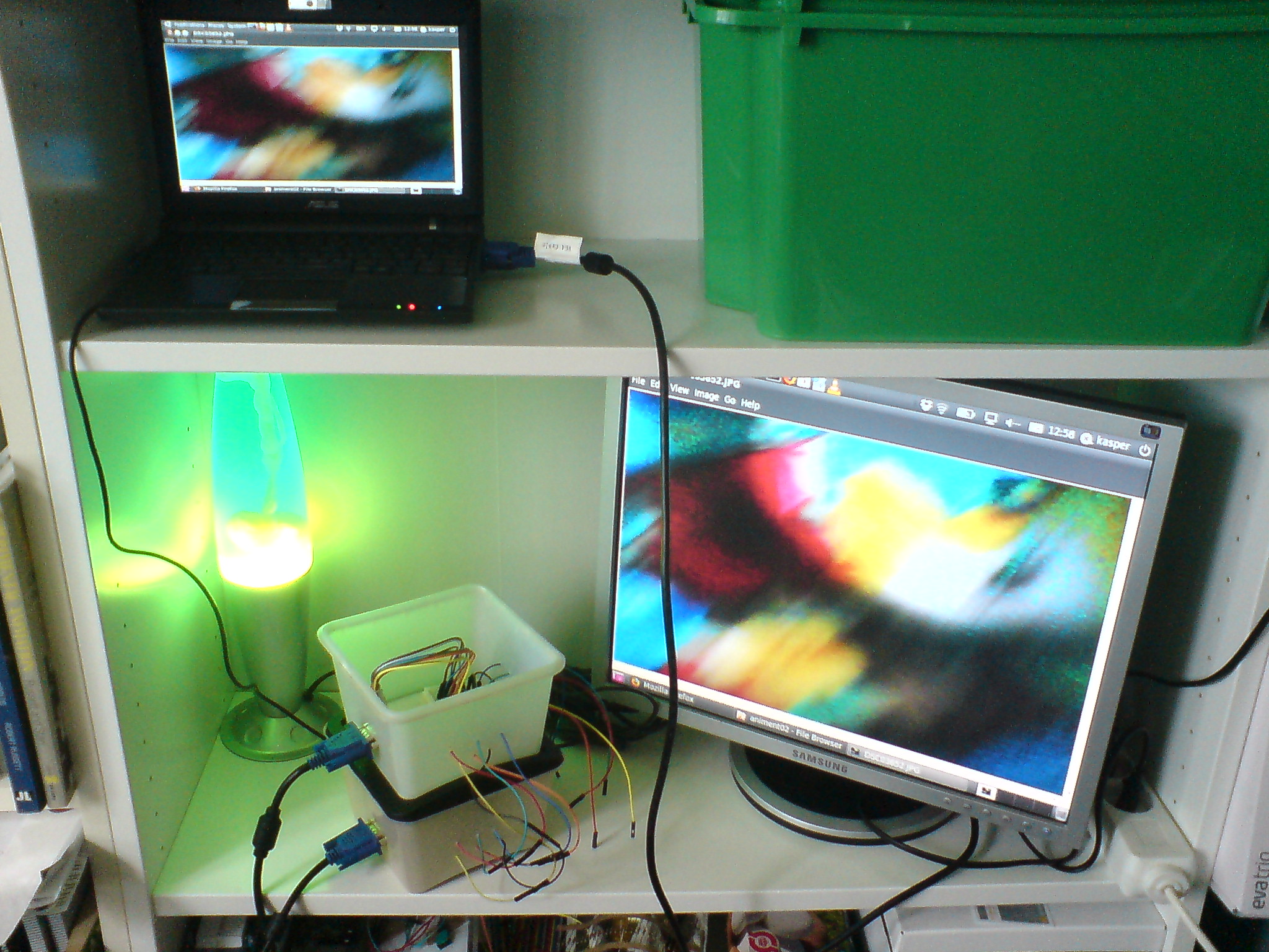
Step 2: Testing
Let's test what you've made so far, and see how we can mount it into a stable module.
First of all, let's optimize the setup, so you only have to deal with 6 wires rather than 10. To manipulate a VGA signal, you will want to hold the 5 pins controlling red, green, blue, h and v separate. But because the five ground pins all goes to 0 volt, you can simplify the setup by connecting these through a breadboard.
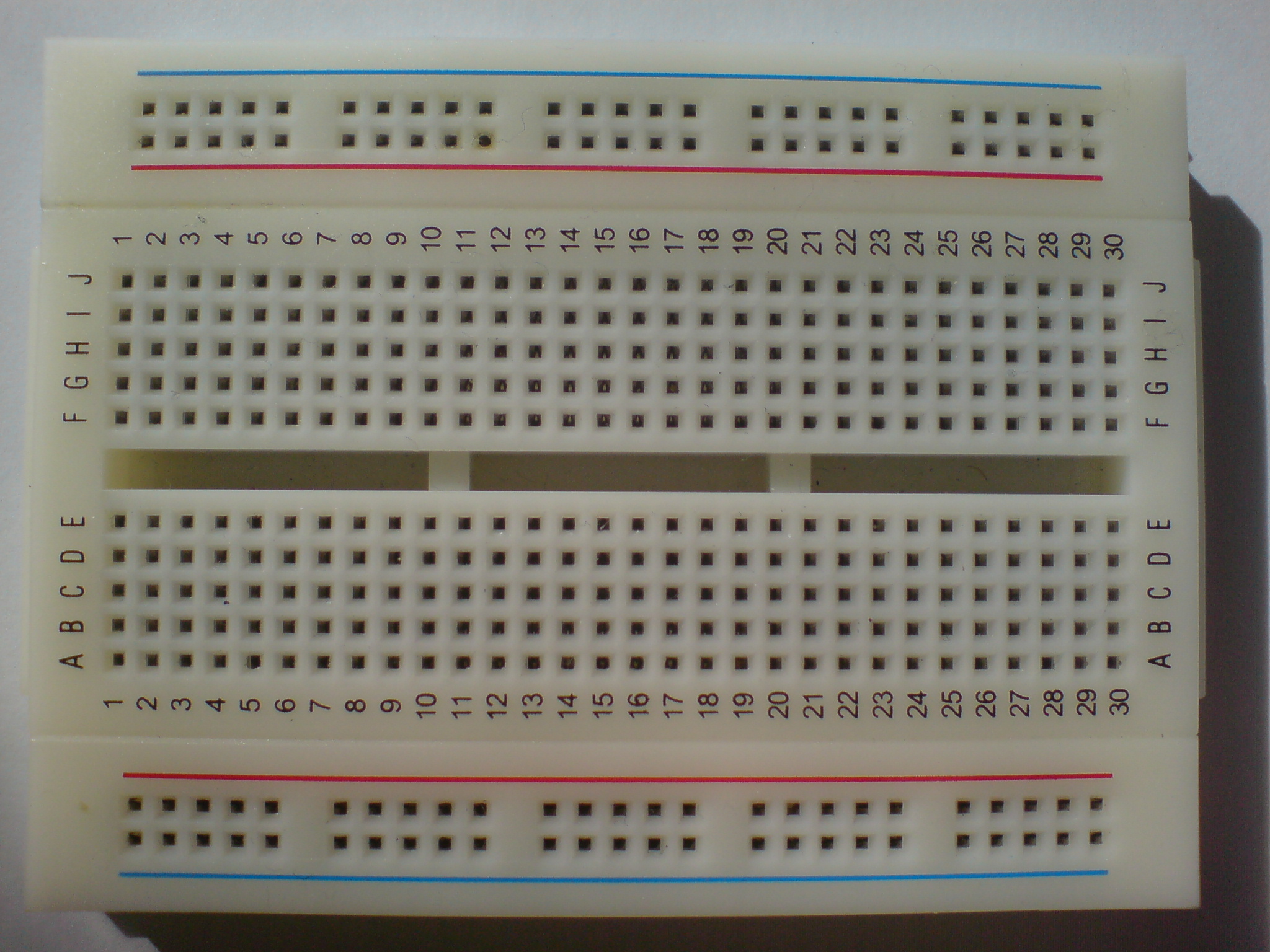 Theory: Breadboard design
A breadboard is basically a [station] that you use to connect jumper wires and other electronic components. The holes on the breadboard are connected at the bottom of the board. The common design is to have two rows at each end which are connected horizontally - these are usually used to provide voltage and ground supply. In between, you have several colomns of holes which are connected in vertical (but not across the "middle" though).
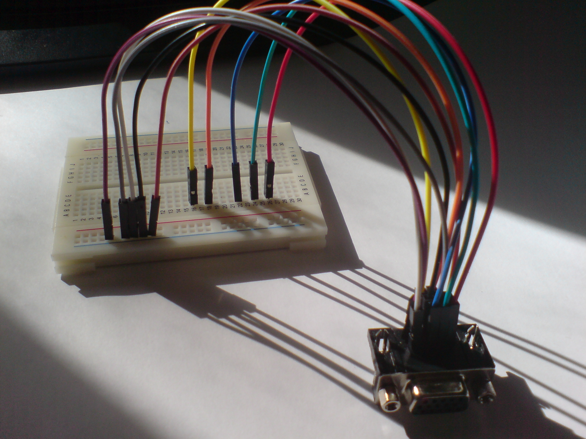
To see if you have connected the wires correctly, try connecting the two sockets through the breadboard. Plug each signal pin from the first socket into a colomn of the breadboard and then plug the corresponding pin from the other socket into the same colomn. Finally, use the two lower rows of the board to connect the ground pins, and connect those two rows with one male-to-male jumper wire.
You can now connect a computer output and a monitor input into either of the sockets, using two VGA cables. If your setup is correct, you will see the computer's output on the monitor.
If it doesn't work
First of all, let's optimize the setup, so you only have to deal with 6 wires rather than 10. To manipulate a VGA signal, you will want to hold the 5 pins controlling red, green, blue, h and v separate. But because the five ground pins all goes to 0 volt, you can simplify the setup by connecting these through a breadboard.
A breadboard is basically a [station] that you use to connect jumper wires and other electronic components. The holes on the breadboard are connected at the bottom of the board. The common design is to have two rows at each end which are connected horizontally - these are usually used to provide voltage and ground supply. In between, you have several colomns of holes which are connected in vertical (but not across the "middle" though).
You can now connect a computer output and a monitor input into either of the sockets, using two VGA cables. If your setup is correct, you will see the computer's output on the monitor.
If it doesn't work
- Go to your computer's graphic card setup and see, if the computer recognizes that you have connected the monitor. Make sure that the graphic card is setup to output a signal through the VGA.
- Make sure that you connected the jumper wires correctly to the socket, and that the wires are still in place.
- If you have a LED and a power supply at hand, you can test each socket connection through sticking a male jumper into the VGA connector's holes, and see if the power goes through.
- You can test each module separately through the Arduino module too (coming soon)
- Google it?
- Find an expert!
Practical note:
My computer usually outputs VGA signals at 800x600 resolution with 60 Hz, when I use this setup. I guess this is the basic setup for a VGA monitor. Monitors come in all sizes and shapes (resolutions and ratios), but because we don't connect the last 5 "information" pins of the VGA connector (which are used to send information about the monitor's dimensions to the computer), you can experience problems with stretched images due to this.
My computer usually outputs VGA signals at 800x600 resolution with 60 Hz, when I use this setup. I guess this is the basic setup for a VGA monitor. Monitors come in all sizes and shapes (resolutions and ratios), but because we don't connect the last 5 "information" pins of the VGA connector (which are used to send information about the monitor's dimensions to the computer), you can experience problems with stretched images due to this.
Step 3: Mounting
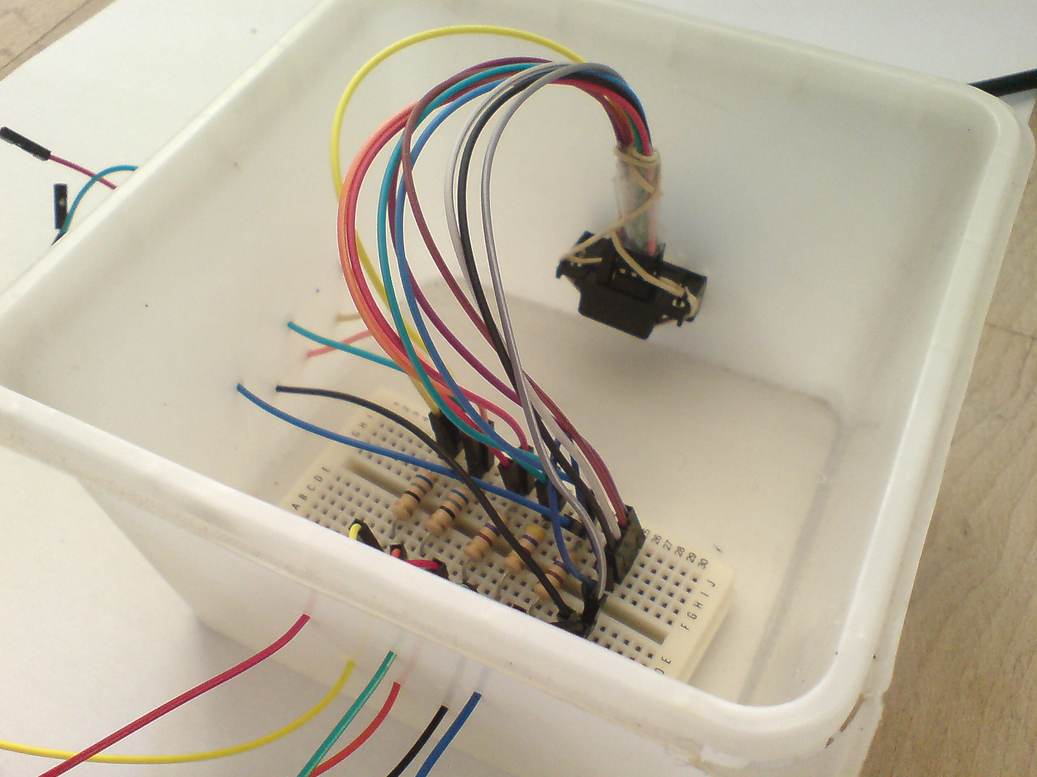
When you're sure that your sockets work, I recommend that you make each one into a stable module by mounting it. This doesn't have to be fancy - I usually use thin plastic boxes because they are strong enough to hold a VGA socket, but are also easy to cut in.
I usually unscrew the two [screws] and put the VGA socket to the outside of the plastic box and draw the outline of the connector. Next, I cut this out, and check if the VGA connector can go into the hole. Then I use a thin, sharp object (like a small screwdriver) to make holes for the two screws, while the VGA connector is in place in the hole.
Unscrew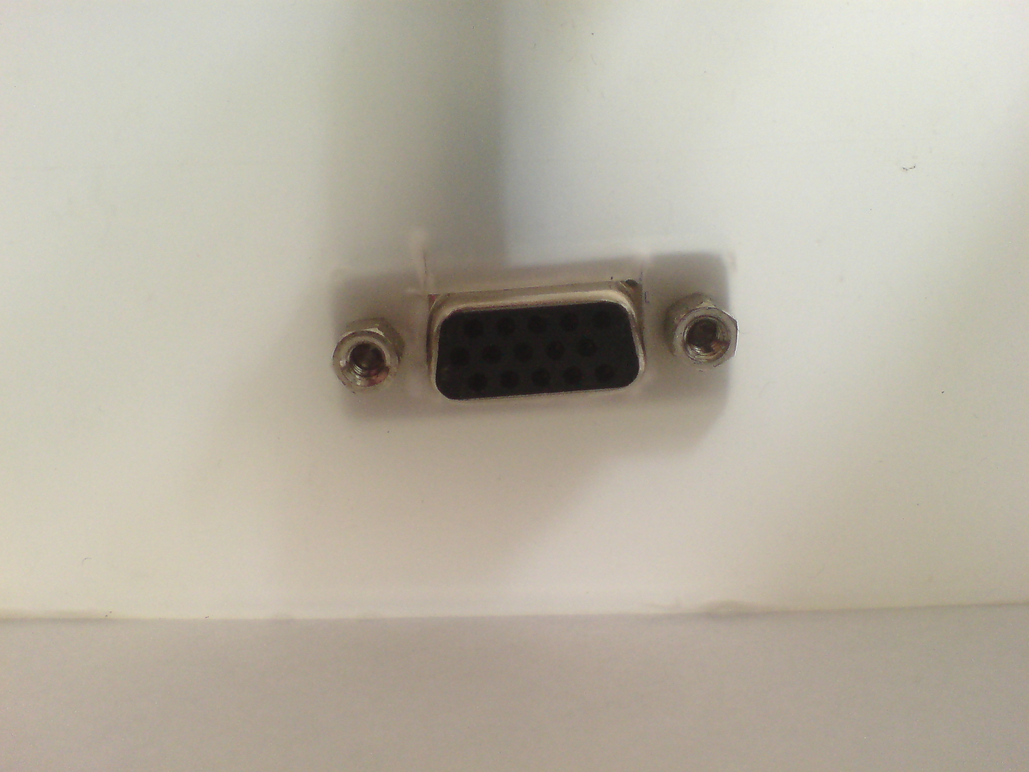
Mounted in box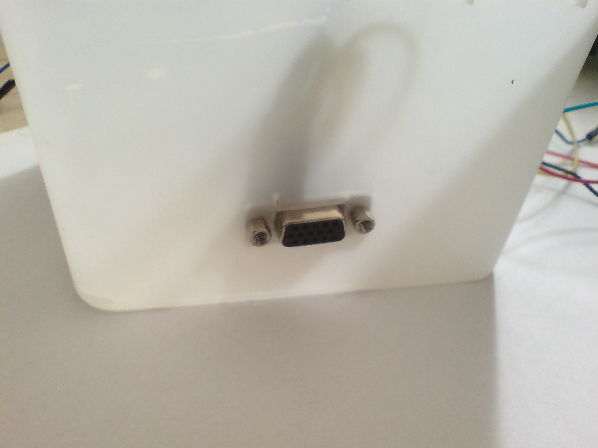
Mounted in box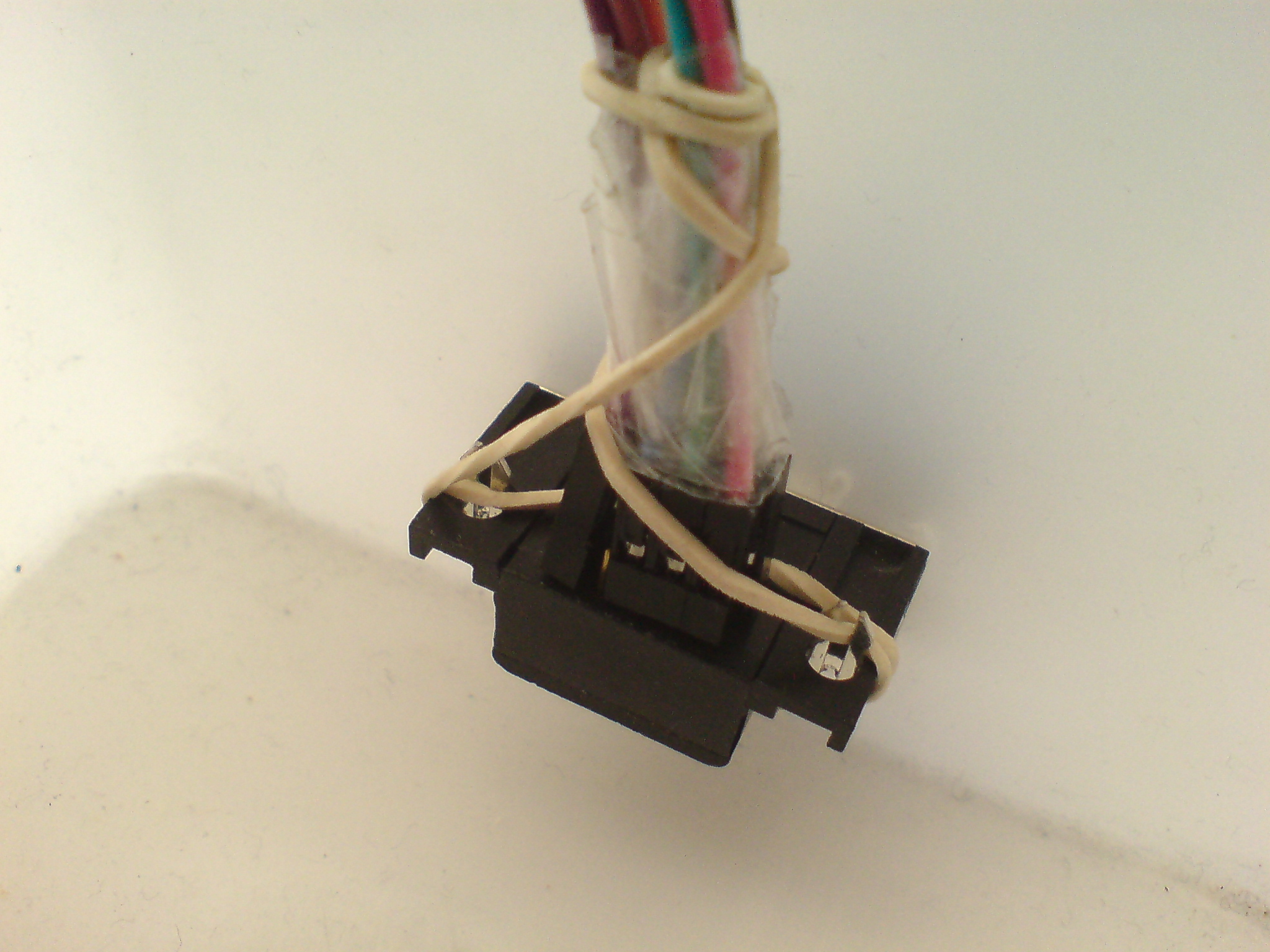
Use tape and rubber band to hold wires in socket
Once the three holes are in place, I make sure the jumper wires are still in place in the socket (using tape and rubber band), and then I put the VGA into the hole from the inside and mount it using the screws.
The KVS Splitter
First, I make six little holes on the one of the sides on the box next to the socket. These holes for the wires to go through. The five signal wires can go directly from the socket and out through the holes, so you can just detach the pin headers on the male end of the wires, and plug them through. Then I plug the ground pins into the lower rows a breadboard (just like before), and use a black male-to-male jumper wire to go from the breadboard row and out of the box.
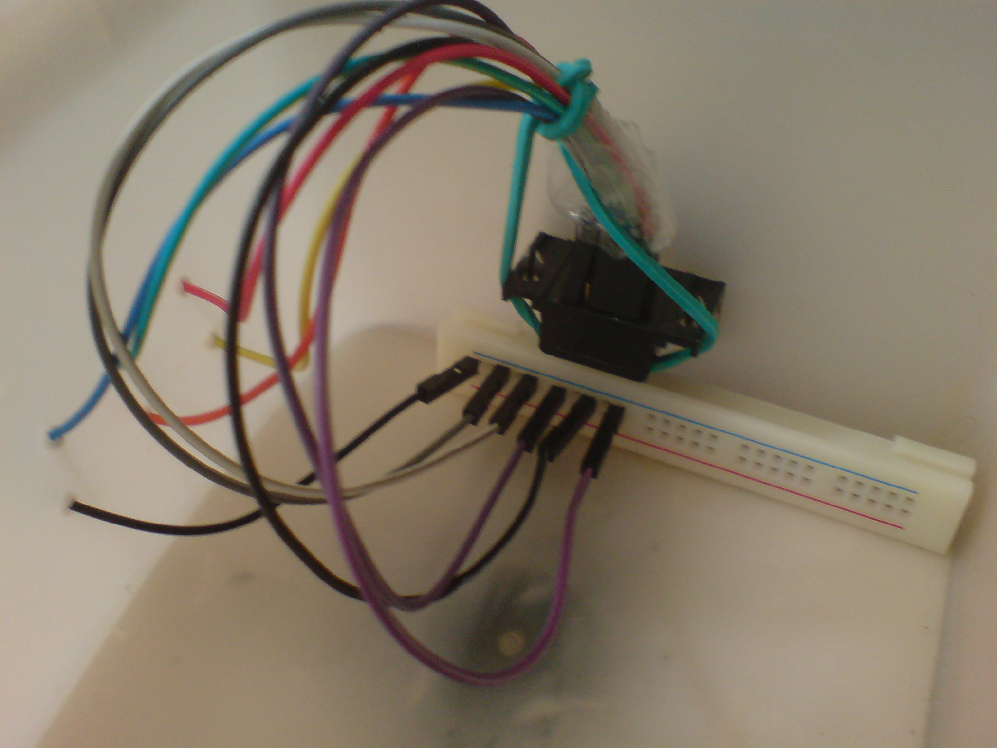
Ground wires from VGA socket are attached to breadboard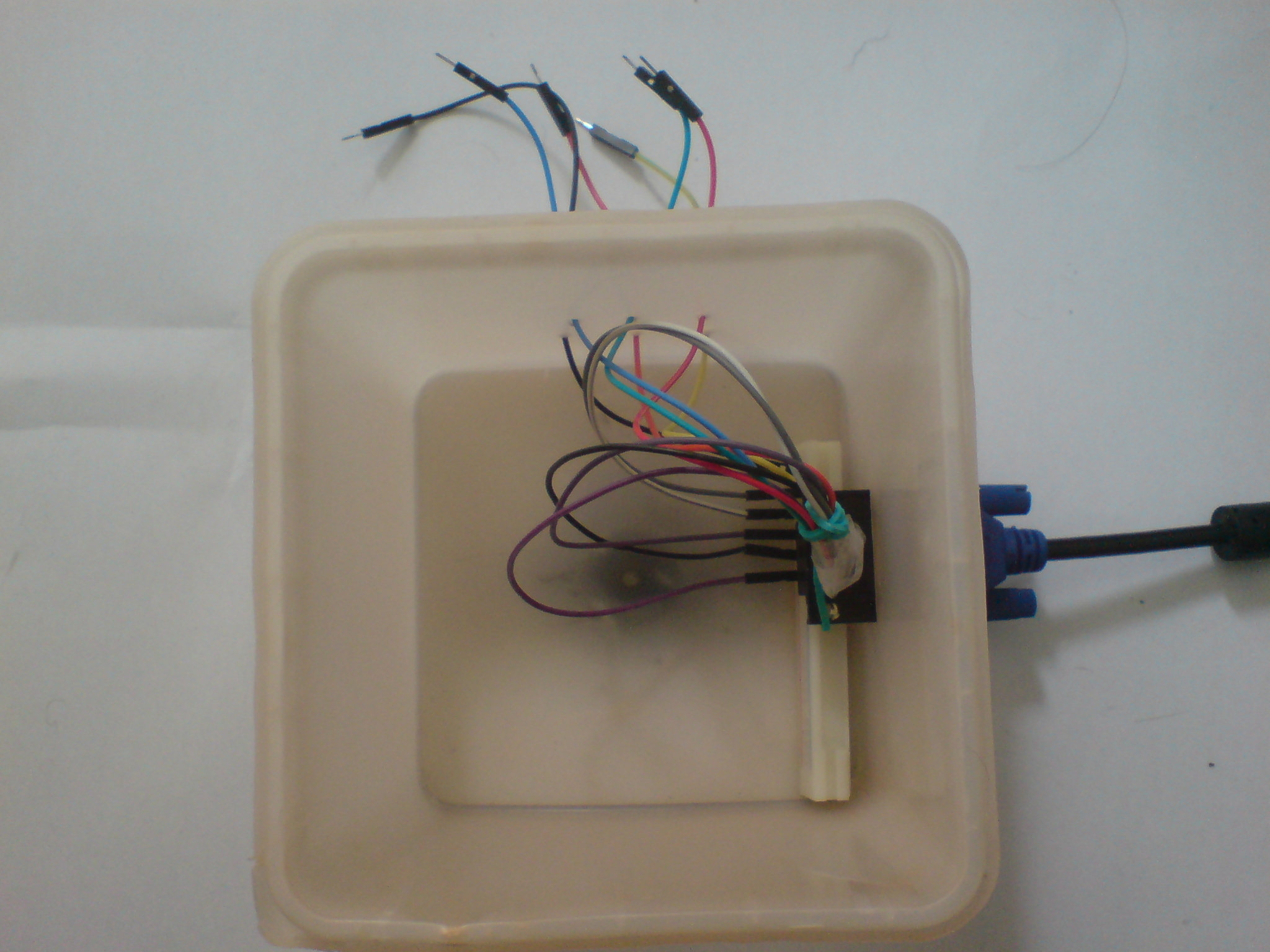
The signal wires and the black wire from breadboard go through the holes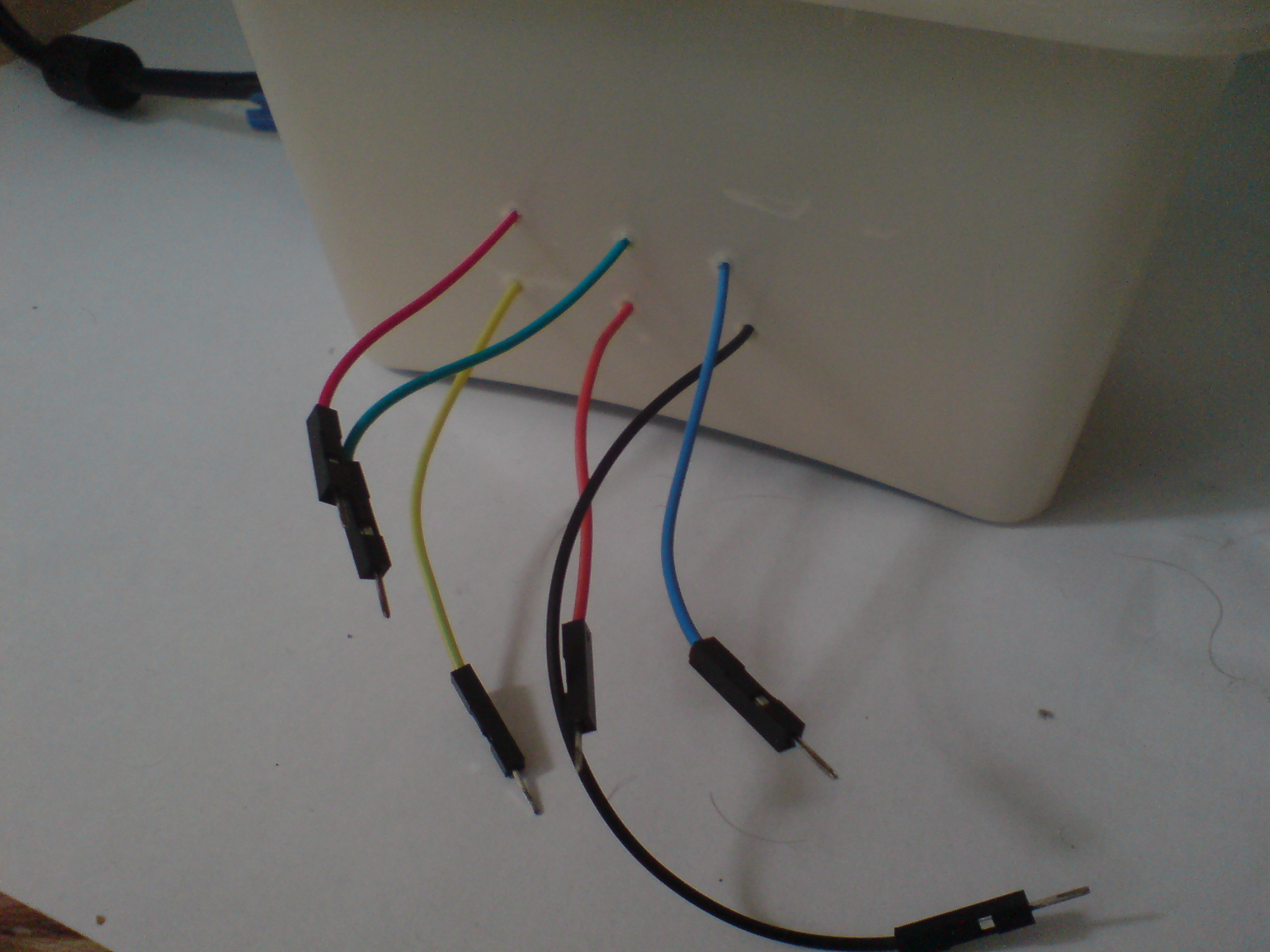
The six wires go outside the box
You can make the KVS Splicer in the same way as the KVS Splitter, to get the first part working. I do, however, recommend one extension which will come in handy if you decide to use Arduino modules from the Kasper Video System.
Because the output of an Arduino is usually too high to work with a monitor (and can potentially damage your screen), I make an additional set of connectors where the monitor is protected by 5 resistors. Once again, you plug the signal pins into separate colomns and attach a male-to-female wire that goes through the holes in the side. But additionally, you use the resistors to connect a signal colomn into a seperate colomn (for example, by crossing the middle of the breadboard). You can then connect the five wires to new male-to-female jumpers that go through the side opposed to the socket (an easy way to tell the resistor input from the non-resistor input), and make six holes for these wires.
Socket into breadboard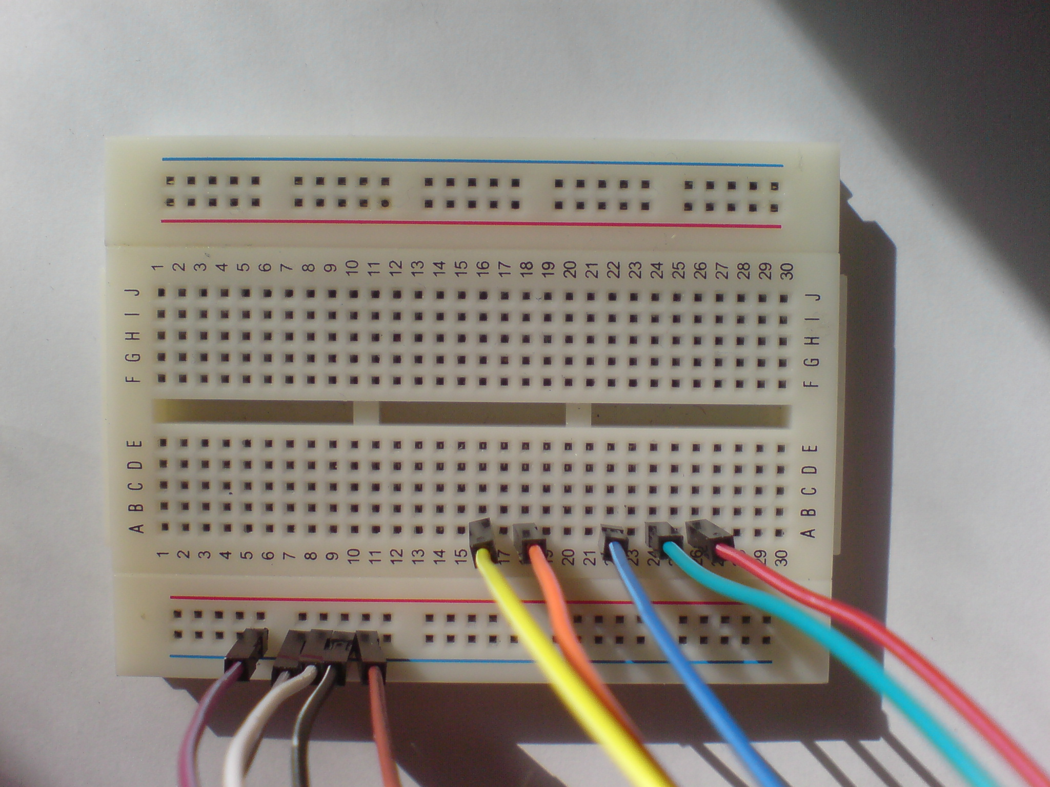
Wires in breadboard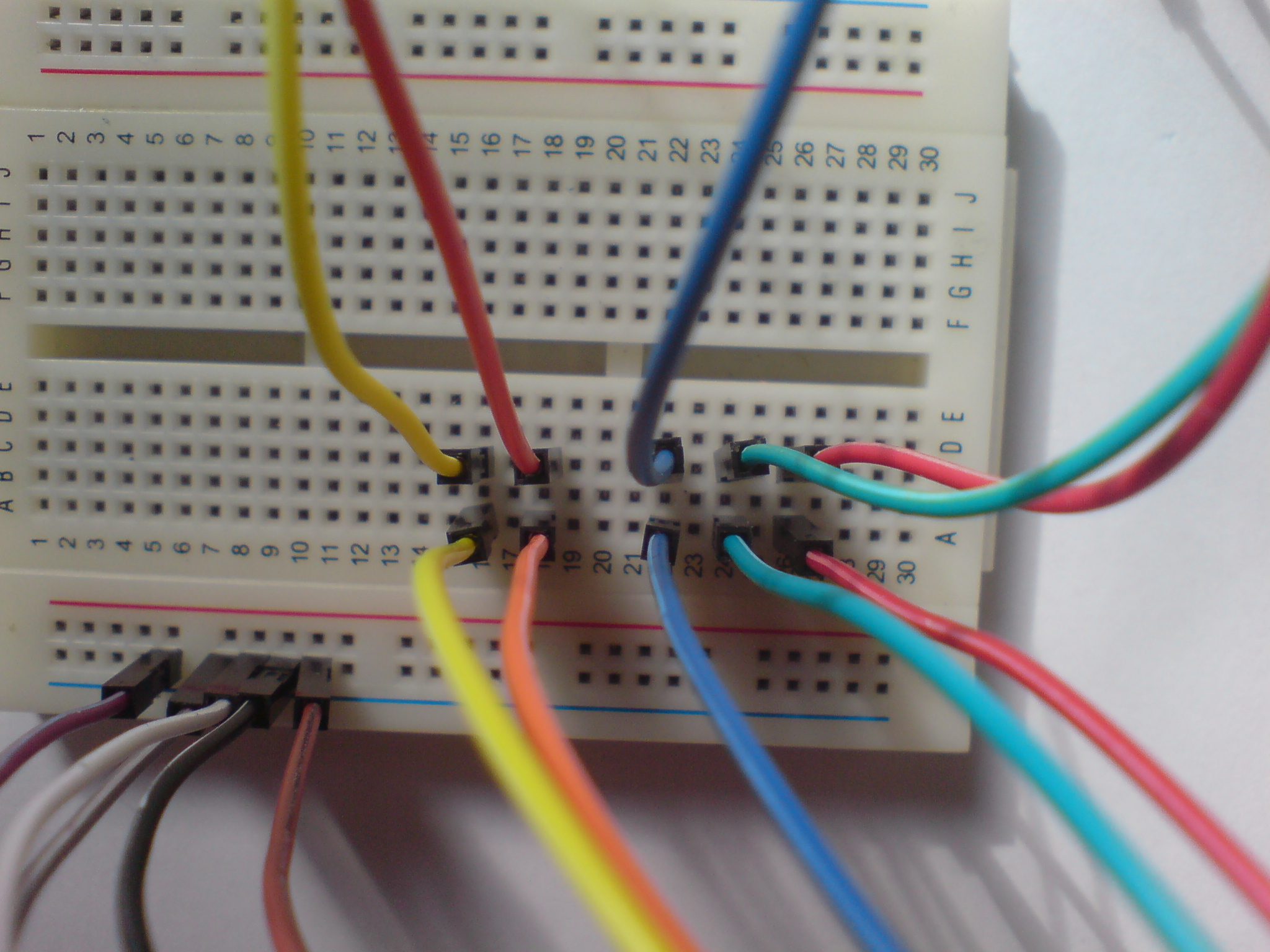
From breadboard to female connectors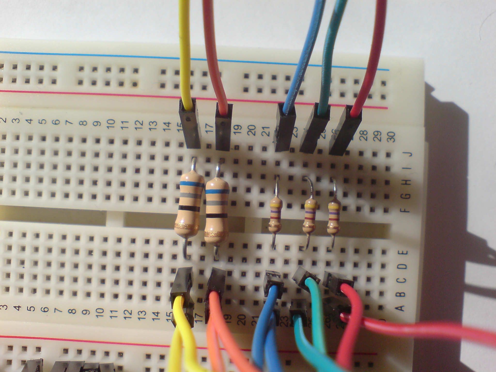
Socket into breadboard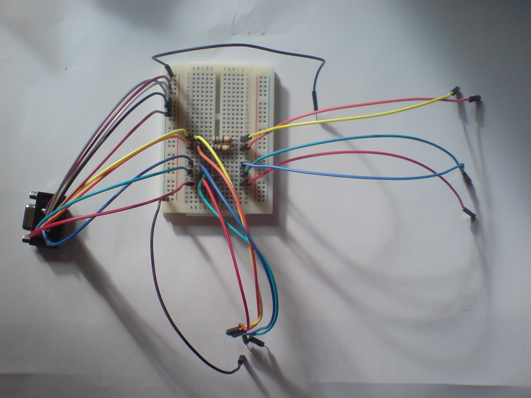
Socket into breadboard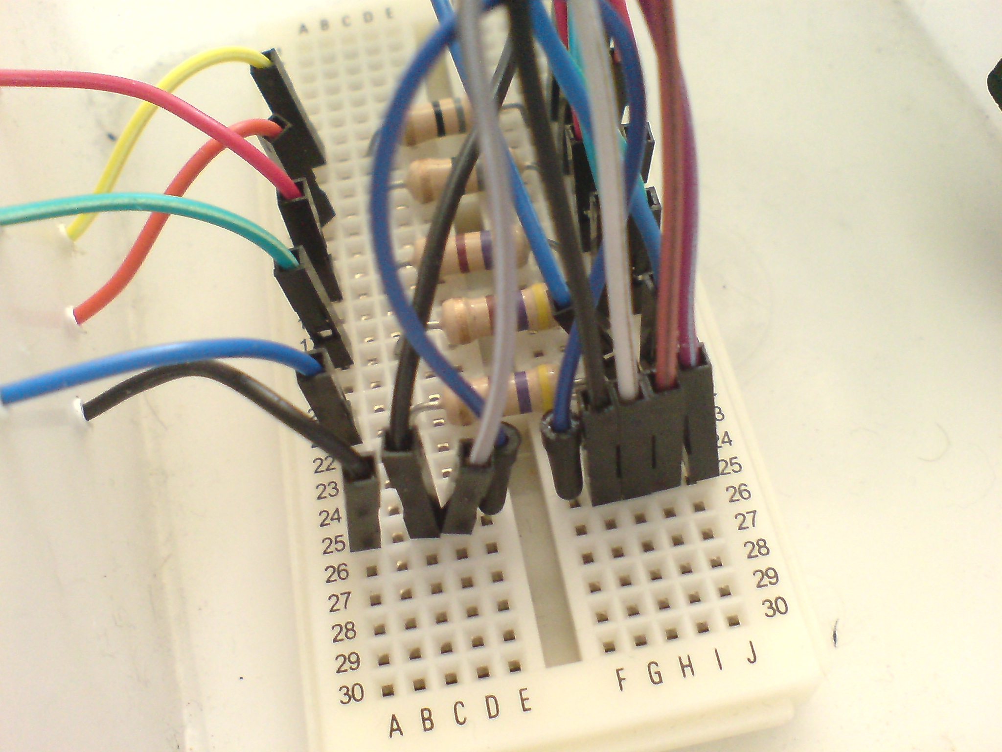
Socket into breadboard
The resistor setup requires that three color channels are connected with a 470 ohm resistor each (color code [yellow, blue, red, gold], and the two sync signals are connected with a 68 ohm resistor each. The ground pins don't need a resistor, so just plug an additional black jumper wire that goes directly to each side of box.
Socket into breadboard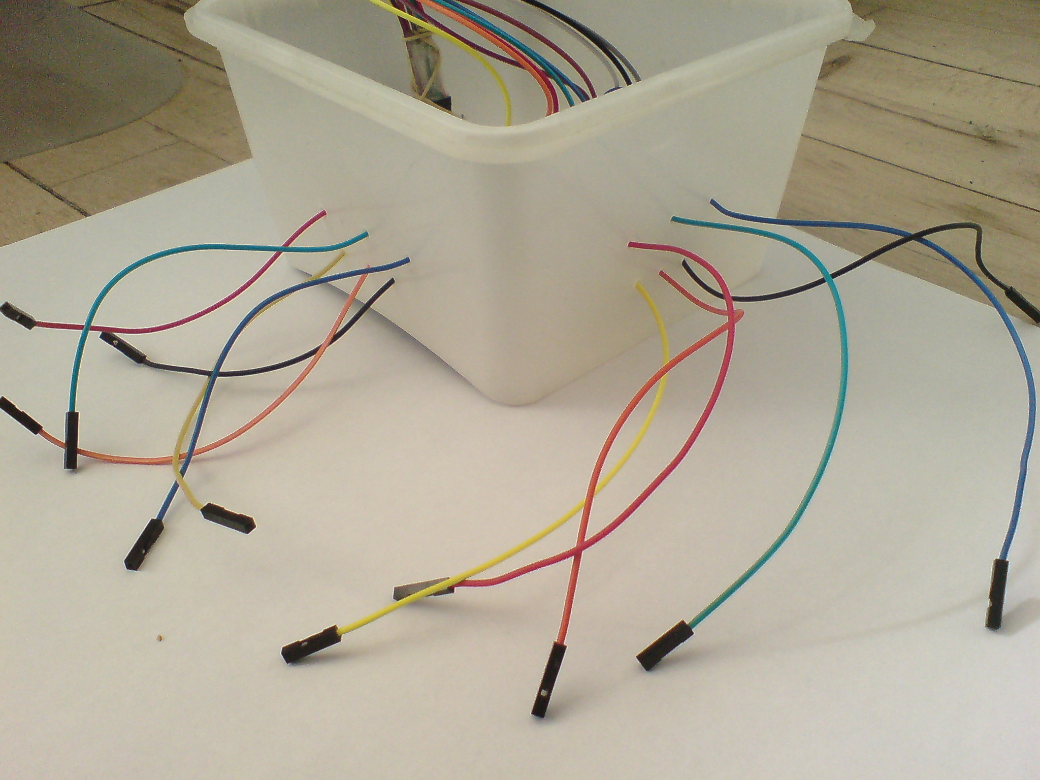
Wires in breadboard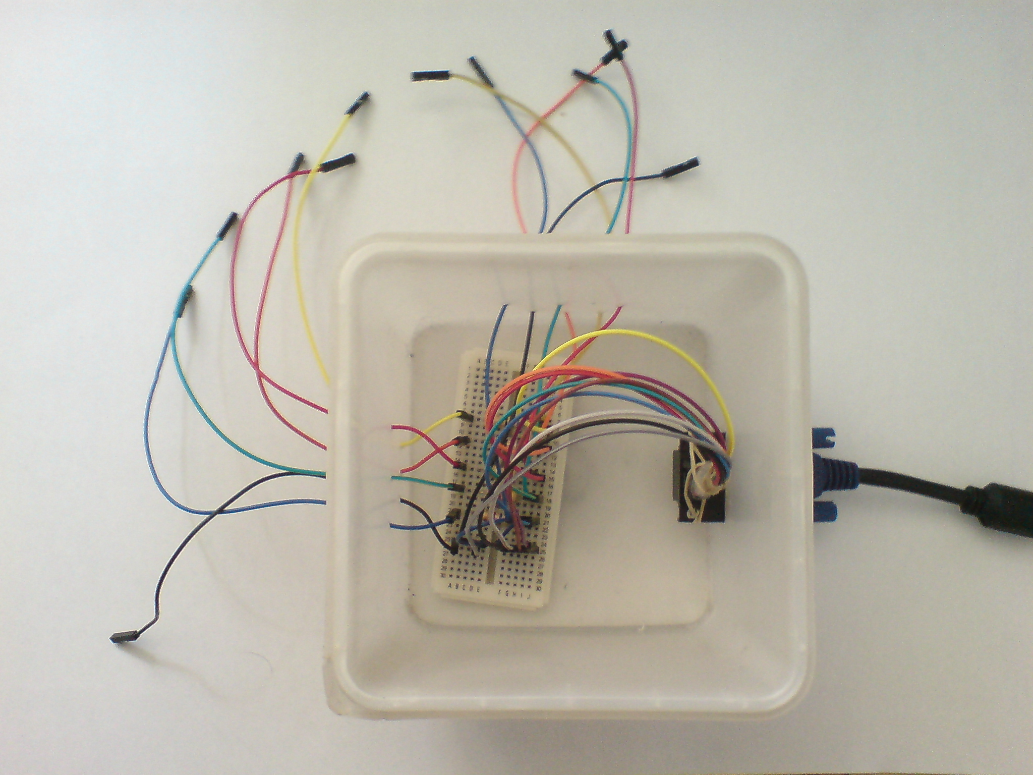
From breadboard to female connectors
I usually unscrew the two [screws] and put the VGA socket to the outside of the plastic box and draw the outline of the connector. Next, I cut this out, and check if the VGA connector can go into the hole. Then I use a thin, sharp object (like a small screwdriver) to make holes for the two screws, while the VGA connector is in place in the hole.
Unscrew
Mounted in box
Mounted in box
Use tape and rubber band to hold wires in socket
The KVS Splitter
First, I make six little holes on the one of the sides on the box next to the socket. These holes for the wires to go through. The five signal wires can go directly from the socket and out through the holes, so you can just detach the pin headers on the male end of the wires, and plug them through. Then I plug the ground pins into the lower rows a breadboard (just like before), and use a black male-to-male jumper wire to go from the breadboard row and out of the box.
Ground wires from VGA socket are attached to breadboard
The signal wires and the black wire from breadboard go through the holes
The six wires go outside the box
PRACTICAL: How to detach and attach pin headers of a jumper wire
The pin headers of a jumper can easily be disassembled in order to get the wire through a small hole in the box. I make a hole that's just right for the wire, detach the pin header of each jumper (using a knife to bend the header up, then pull the wire out), stick it through the hole, and attach it again.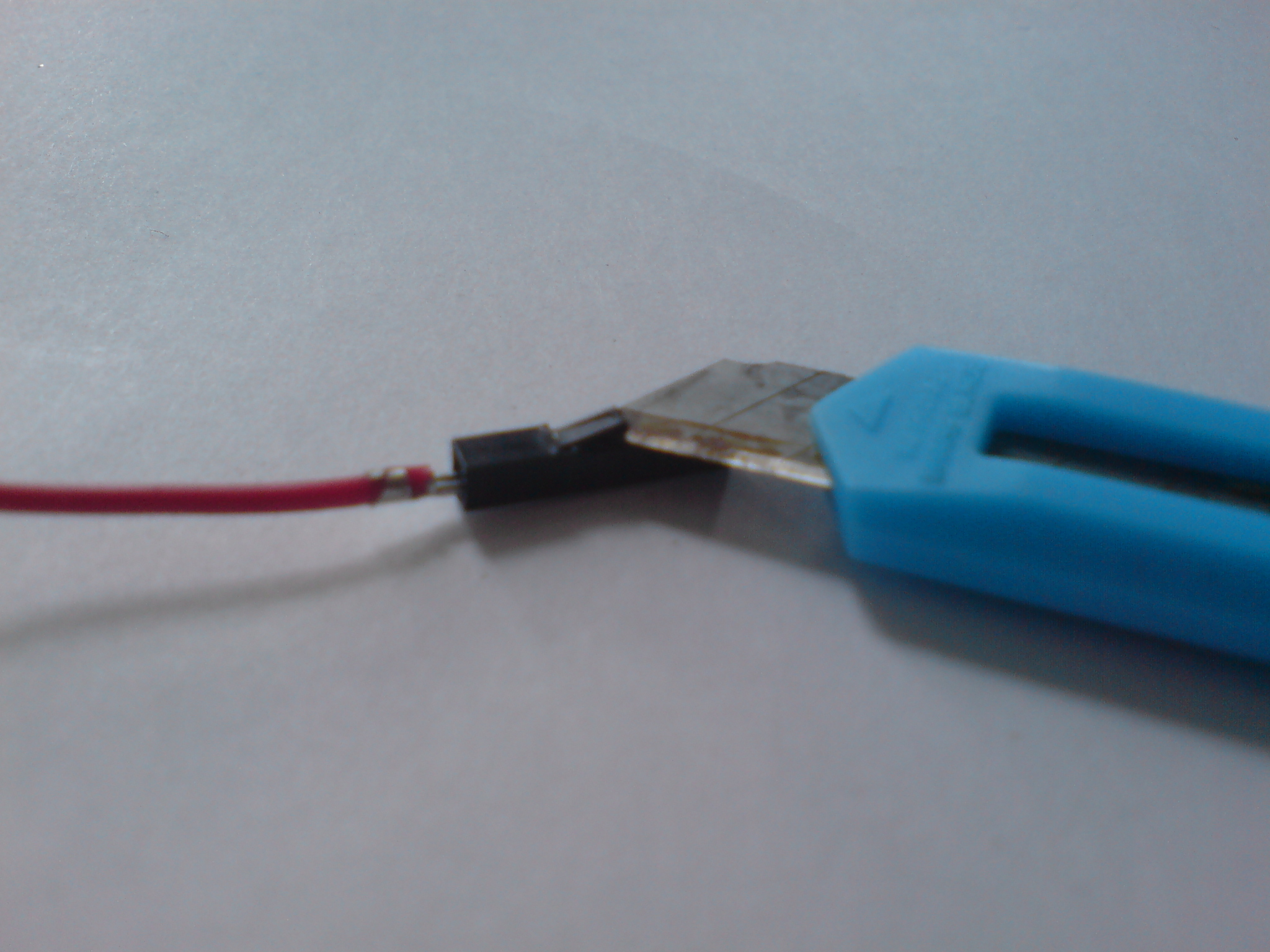
Use sharp tool to release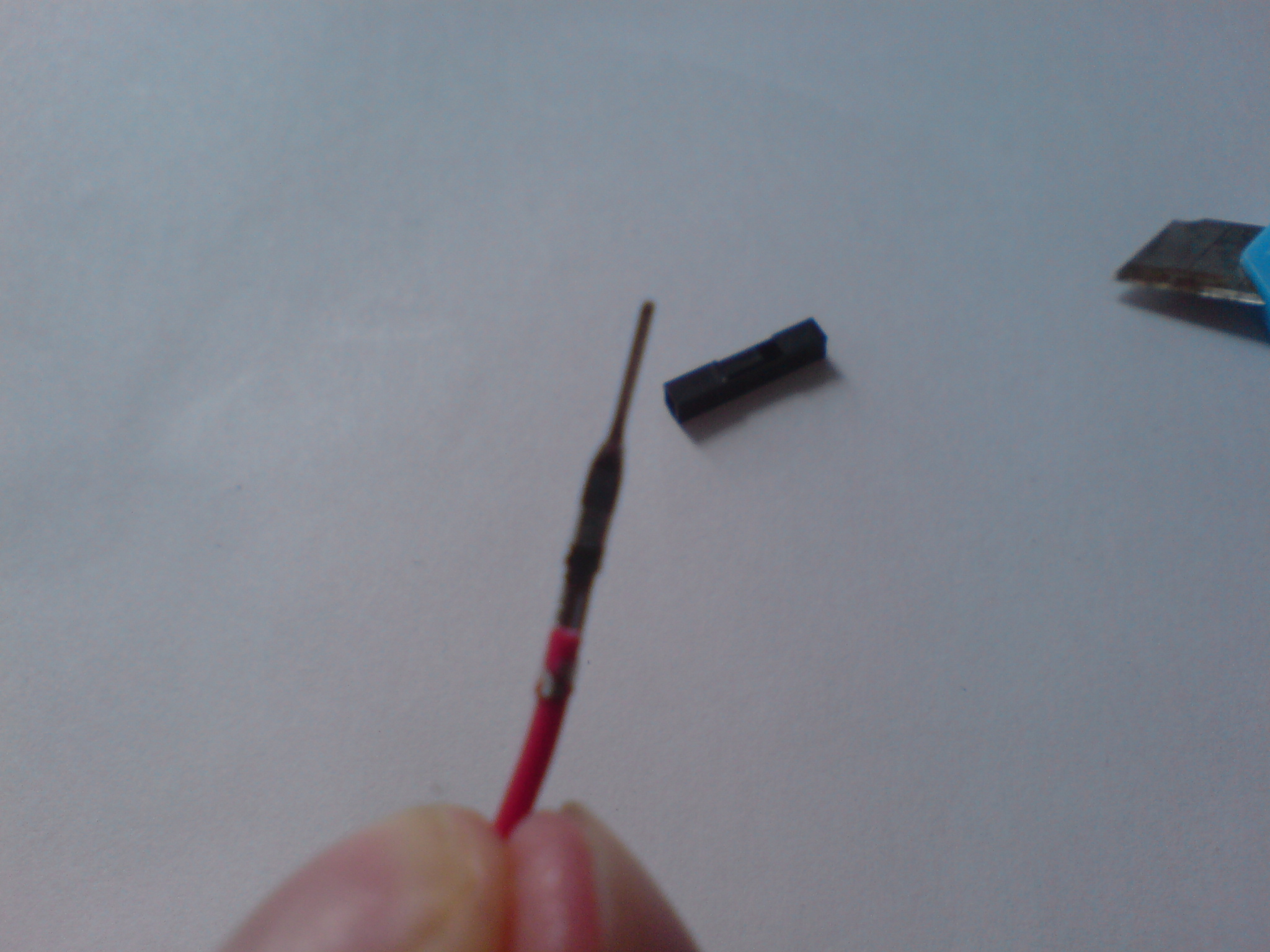
Pin and header are separated
The KVS SplicerThe pin headers of a jumper can easily be disassembled in order to get the wire through a small hole in the box. I make a hole that's just right for the wire, detach the pin header of each jumper (using a knife to bend the header up, then pull the wire out), stick it through the hole, and attach it again.
Use sharp tool to release
Pin and header are separated
You can make the KVS Splicer in the same way as the KVS Splitter, to get the first part working. I do, however, recommend one extension which will come in handy if you decide to use Arduino modules from the Kasper Video System.
Because the output of an Arduino is usually too high to work with a monitor (and can potentially damage your screen), I make an additional set of connectors where the monitor is protected by 5 resistors. Once again, you plug the signal pins into separate colomns and attach a male-to-female wire that goes through the holes in the side. But additionally, you use the resistors to connect a signal colomn into a seperate colomn (for example, by crossing the middle of the breadboard). You can then connect the five wires to new male-to-female jumpers that go through the side opposed to the socket (an easy way to tell the resistor input from the non-resistor input), and make six holes for these wires.
Socket into breadboard
Wires in breadboard
From breadboard to female connectors
Socket into breadboard
Socket into breadboard
Socket into breadboard
System note: Male to female order of the Kasper Video System
I use male-to-male wires for the KVS Splitter and male-to-female wires for the KVS Splicer, because in that way you can connect the modules directly to each other. Furthermore, this reflects the order that a male connector represents an output and a female connector represents an input in the flow of the overall system. [image]
I use male-to-male wires for the KVS Splitter and male-to-female wires for the KVS Splicer, because in that way you can connect the modules directly to each other. Furthermore, this reflects the order that a male connector represents an output and a female connector represents an input in the flow of the overall system. [image]
Socket into breadboard
Wires in breadboard
From breadboard to female connectors
Step 4: Changing colors of a VGA signal
Once you have the sockets and wires mounted, you should test the modules by connecting each of the six wires to it's respective color. You should see the output from the computer on the monitor again.
Now, it's time for your first experiment with VGA video synthesis. Try unplugging each connection between the modules, and see how this affects the image.
When you unplug the color pins, the respective color should disappear from the image.
When you unplug the sync pins, the monitor will go black (or in "searching" mode) because it doesn't think that there is a signal anymore.
When you unplug the ground pins, the monitor either goes black, or produces a darkened version of the original image.
Connecting red wire only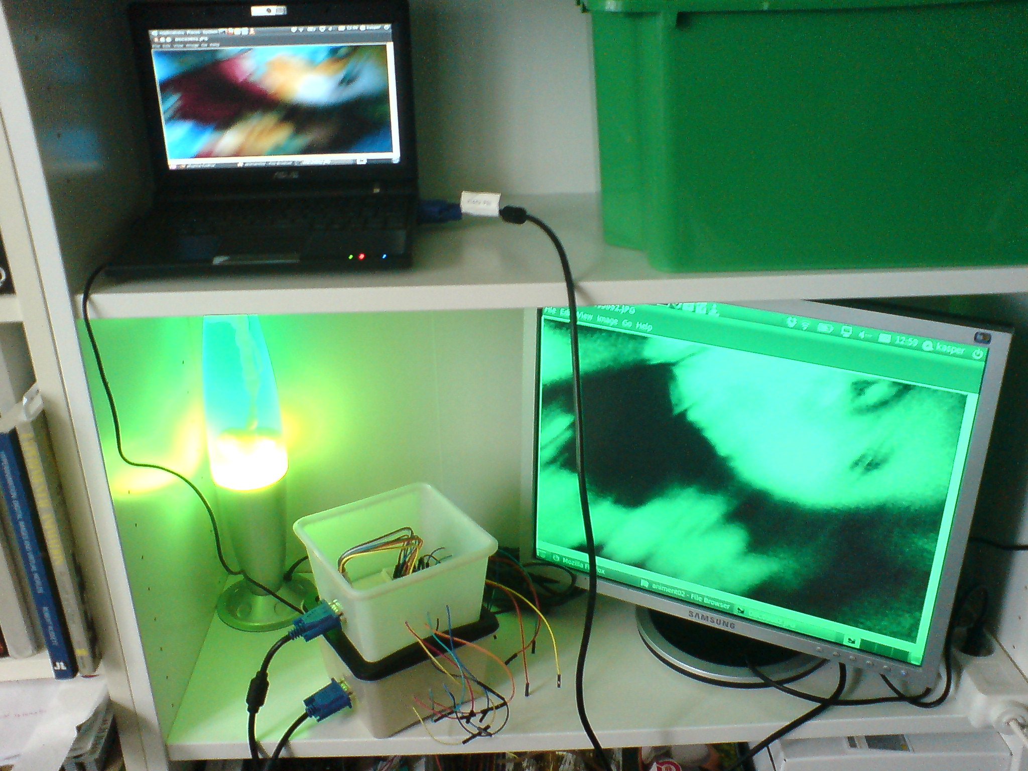
Connecting green wire only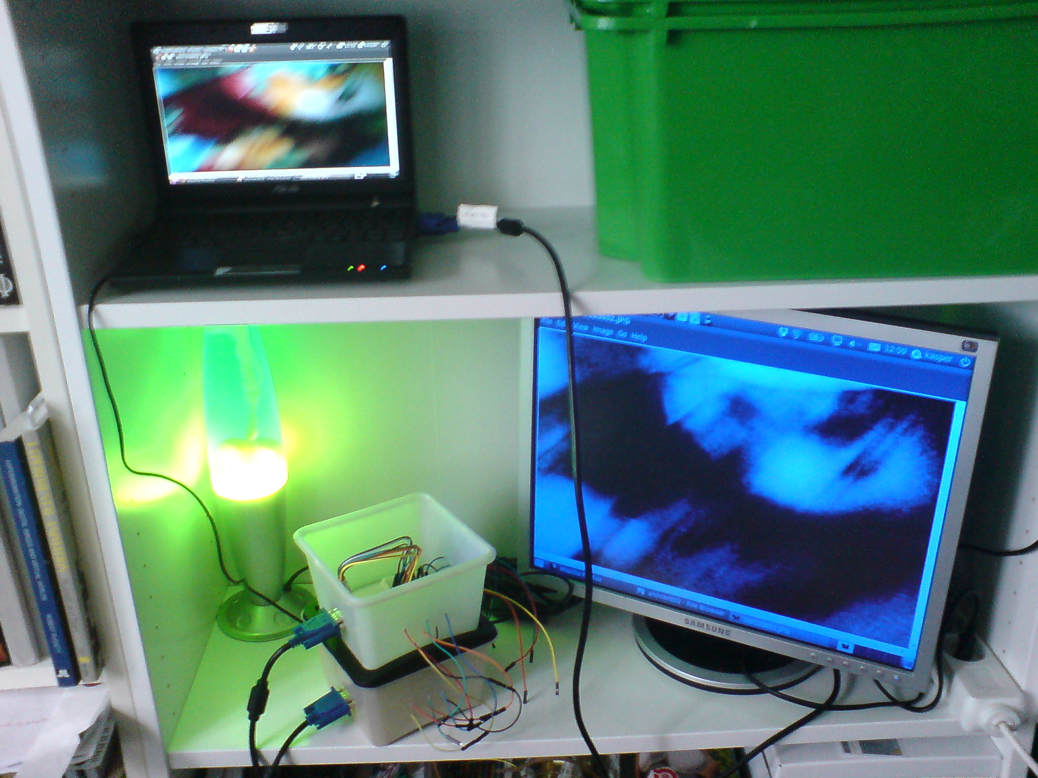
Connecting blue wire only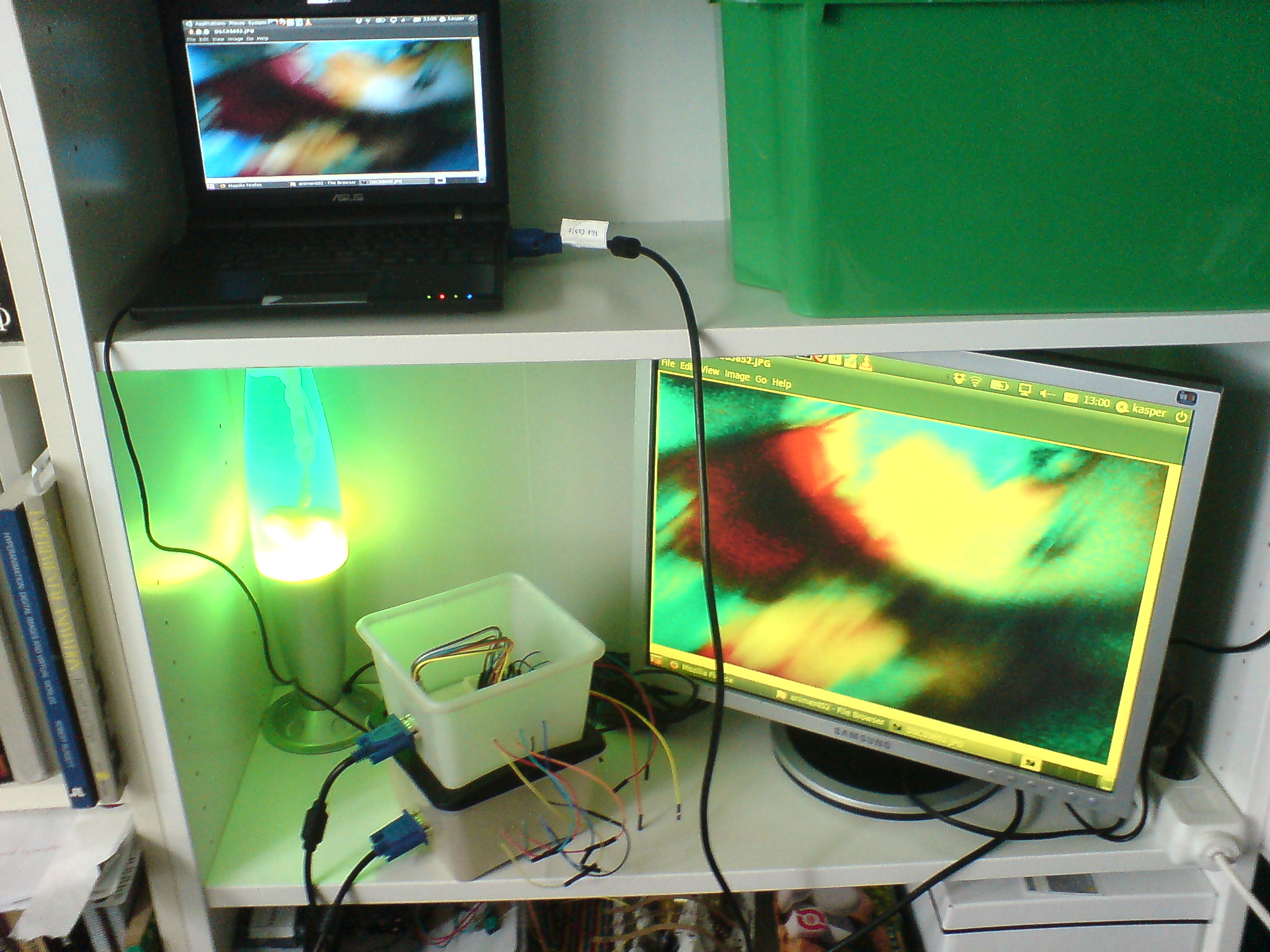
Connecting red and green wire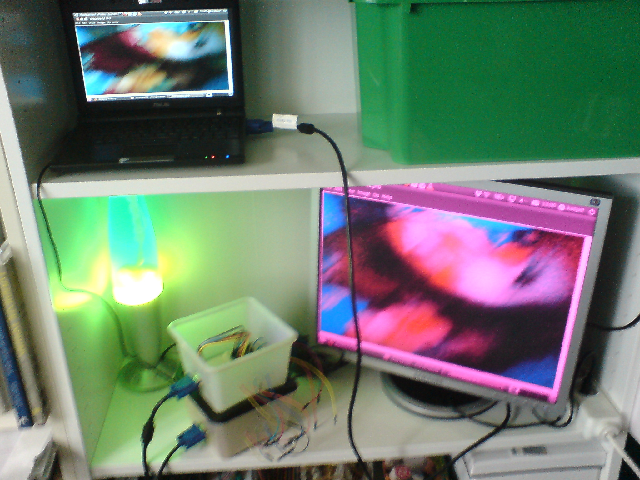
Connecting red and blue wire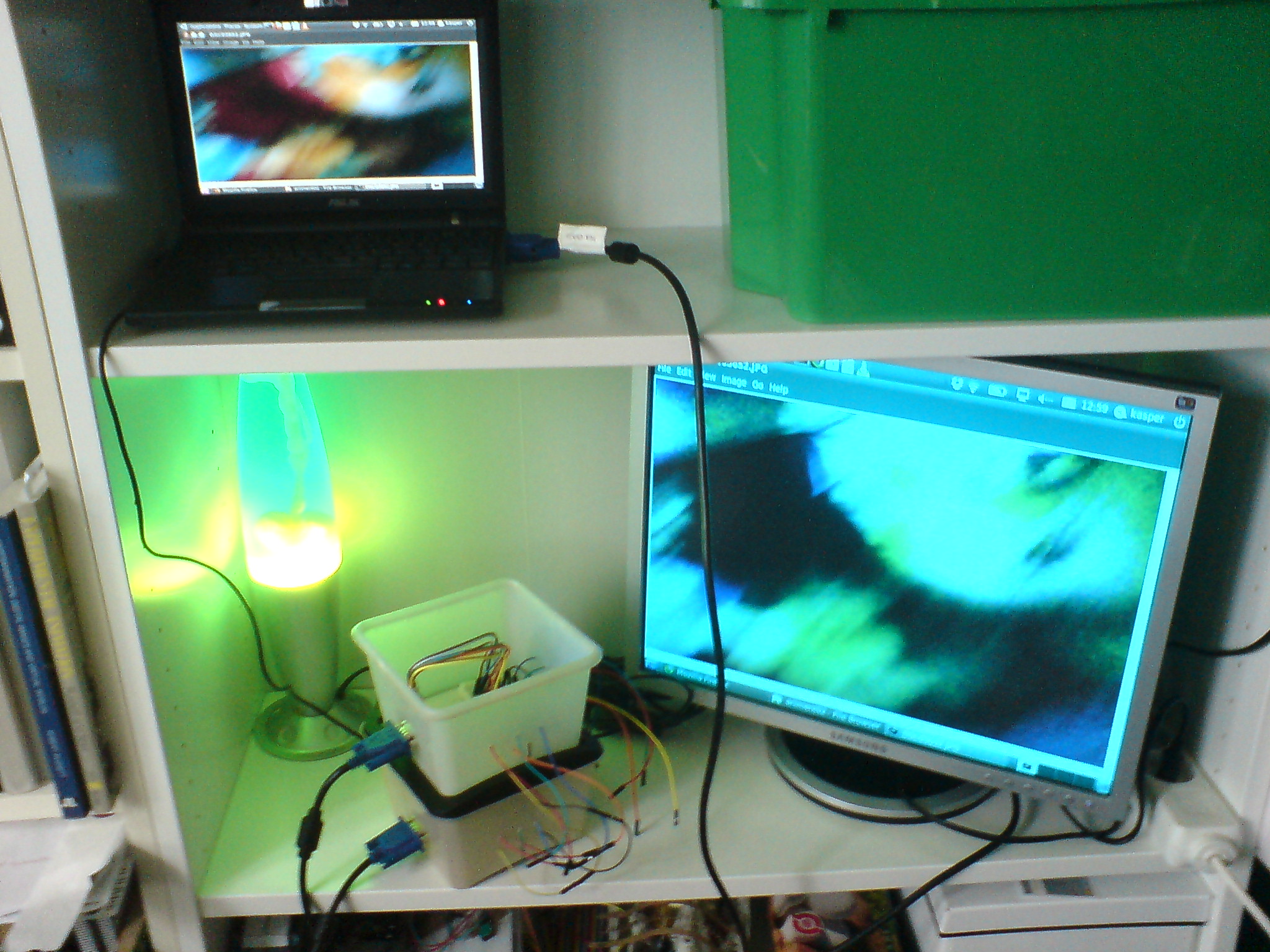
Connecting green and blue wires
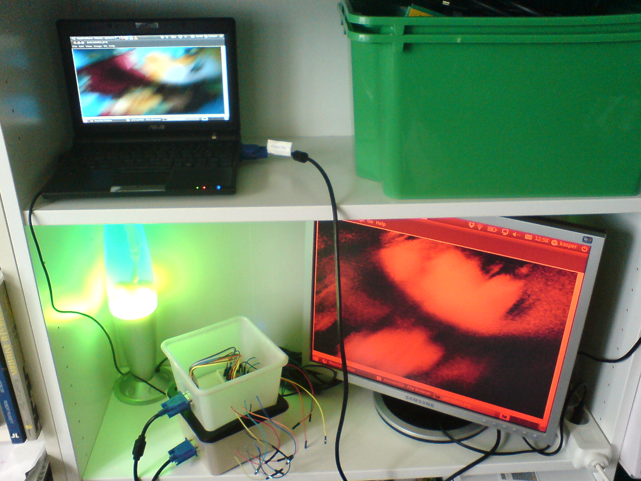
After that, try changing the connections between the color pins. For example, plug the red male wire into the green female wire, and see what happens. The red on the computer image is translated into a green image on the monitor. The VGA signal doesn't understand "color" - it just outputs the lightness (or luminance) contained in the electronic signal into a color channel. This is the basic principle of video synthesis.
Red to red, green to green, blue to blue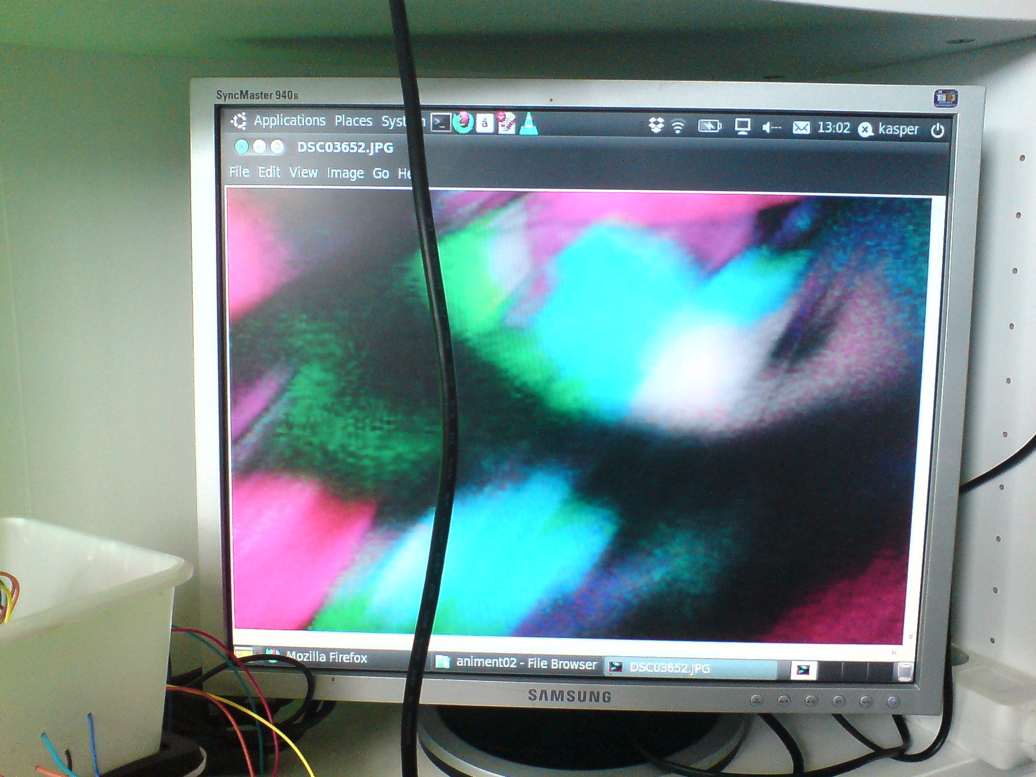
Red to green, green to blue, blue to red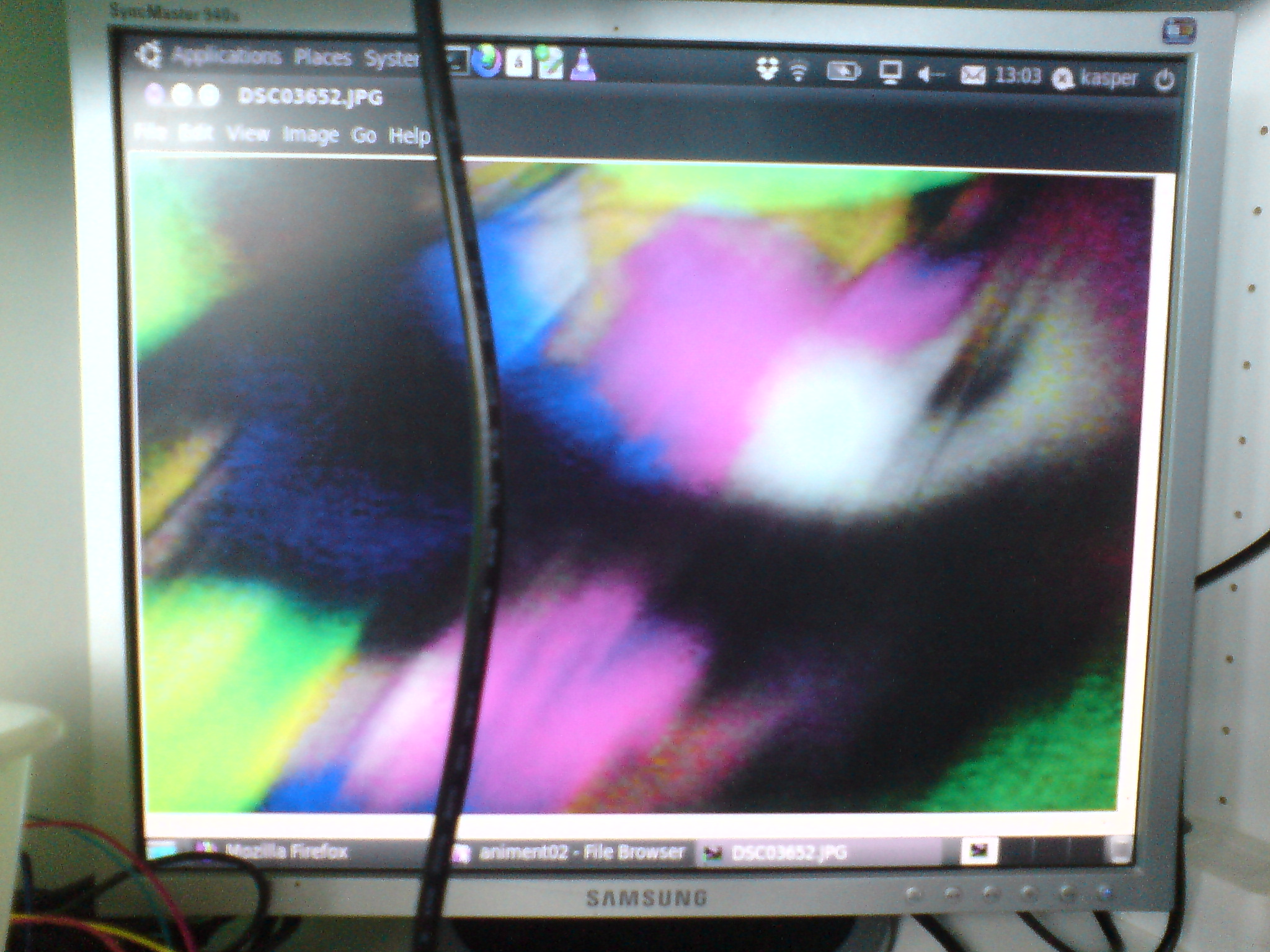
Red to blue, green to red, blue to green
Finally, if you made a resistor side of the KVS Splicer, try connecting one of the color wires from the KVS Splitter to this [side] instead. Because there's a 470 ohm resistance on the connection, the corresponding color will be darkened when it reaches the monitor.
Now, it's time for your first experiment with VGA video synthesis. Try unplugging each connection between the modules, and see how this affects the image.
When you unplug the color pins, the respective color should disappear from the image.
When you unplug the sync pins, the monitor will go black (or in "searching" mode) because it doesn't think that there is a signal anymore.
When you unplug the ground pins, the monitor either goes black, or produces a darkened version of the original image.
Connecting red wire only
Connecting green wire only
Connecting blue wire only
Connecting red and green wire
Connecting red and blue wire
Connecting green and blue wires
After that, try changing the connections between the color pins. For example, plug the red male wire into the green female wire, and see what happens. The red on the computer image is translated into a green image on the monitor. The VGA signal doesn't understand "color" - it just outputs the lightness (or luminance) contained in the electronic signal into a color channel. This is the basic principle of video synthesis.
Red to red, green to green, blue to blue
Red to green, green to blue, blue to red
Red to blue, green to red, blue to green
Congratulations
You have now made two basic modules of the Kasper Video System and is ready to experiment with further video synthesis. I encourage you to play around with this setup on your own, so you can get a sense of how the VGA signal works and can be manipulated.
When you're curious to make more modules, you can continue to the KVS Mixer module.
When you're curious to make more modules, you can continue to the KVS Mixer module.

Filmmaskiner.dk by Kasper Lauritzen is licensed under a Creative Commons Attribution-NonCommercial-ShareAlike 4.0 International License.