KVS Checkbox
Goal
To make the KVS Checkbox which can generate simple image patterns.
Please notice that this is essentially a clone of Gammon's brilliant Arduino project, so all credits go to his talent and generosity. Please respect his copyright notice in the code.
You will also learn
To make the KVS Checkbox which can generate simple image patterns.
Please notice that this is essentially a clone of Gammon's brilliant Arduino project, so all credits go to his talent and generosity. Please respect his copyright notice in the code.
You will also learn
- What is an Arduino and how do I use it?
- What is additive color process?
Try this at your own risk!
I'm sharing these documents in the spirit of DIY and creative commons. It's basically the tutorial I wish I had had when I became interested in making video synthesis. I am, however, not an authorized electrician or engineer, so if you decide trying these things you do so at your own risk and take full responsibility of any harms done to yourself, the hardware in use, our Earth and the universe in general.
I'm sharing these documents in the spirit of DIY and creative commons. It's basically the tutorial I wish I had had when I became interested in making video synthesis. I am, however, not an authorized electrician or engineer, so if you decide trying these things you do so at your own risk and take full responsibility of any harms done to yourself, the hardware in use, our Earth and the universe in general.
You will need
- Arduino Uno
- USB cable to Arduino
- 6 Male-to-male jumper wires (red, green, blue, orange, yellow and black)
- The KVS collector (full edition - with resistors)
- Computer with *Arduino IDE software* installed
Step 1: Upload code to the Arduino Uno
This digital module uses an Arduino and requires a computer to program it. Install the Arduino IDE Software on your computer, connect the Arduino to the computer (with USB cable) and upload Nick Gammon's program for checkbox pattern:
Next, you have to add a file called "TimerHelpers.h" to the project. Save the project you're working on. Then go to the directory and create an empty text file called "TimerHelpers.h" (make sure ".h" is the filetype). Add the code below to this document, save it and use "Sketch > Add File..." in Arduino IDE's menu to add the helper code. It should now open as a new tab in the project window.
The code for TimerHelpers.h is:
/* VGA colour video generation Author: Nick Gammon Date: 22nd April 2012 Version: 1.0 Version 1.0: initial release Connections: D3 : Horizontal Sync (68 ohms in series) --> Pin 13 on DB15 socket D4 : Red pixel output (470 ohms in series) --> Pin 1 on DB15 socket D5 : Green pixel output (470 ohms in series) --> Pin 2 on DB15 socket D6 : Blue pixel output (470 ohms in series) --> Pin 3 on DB15 socket D10 : Vertical Sync (68 ohms in series) --> Pin 14 on DB15 socket Gnd : --> Pins 5, 6, 7, 8, 10 on DB15 socket Note: As written, this sketch has 34 bytes of free SRAM memory. PERMISSION TO DISTRIBUTE Permission is hereby granted, free of charge, to any person obtaining a copy of this software and associated documentation files (the "Software"), to deal in the Software without restriction, including without limitation the rights to use, copy, modify, merge, publish, distribute, sublicense, and/or sell copies of the Software, and to permit persons to whom the Software is furnished to do so, subject to the following conditions: The above copyright notice and this permission notice shall be included in all copies or substantial portions of the Software. LIMITATION OF LIABILITY The software is provided "as is", without warranty of any kind, express or implied, including but not limited to the warranties of merchantability, fitness for a particular purpose and noninfringement. In no event shall the authors or copyright holders be liable for any claim, damages or other liability, whether in an action of contract, tort or otherwise, arising from, out of or in connection with the software or the use or other dealings in the software. */ #include#include #include const byte hSyncPin = 3; // <------- HSYNC const byte redPin = 4; // <------- Red pixel data const byte greenPin = 5; // <------- Green pixel data const byte bluePin = 6; // <------- Blue pixel data const byte vSyncPin = 10; // <------- VSYNC const int horizontalBytes = 60; // 480 pixels wide const int verticalPixels = 480; // 480 pixels high // Timer 1 - Vertical sync // output OC1B pin 16 (D10) <------- VSYNC // Period: 16.64 mS (60 Hz) // 1/60 * 1e6 = 16666.66 uS // Pulse for 64 uS (2 x HSync width of 32 uS) // Sync pulse: 2 lines // Back porch: 33 lines // Active video: 480 lines // Front porch: 10 lines // Total: 525 lines // Timer 2 - Horizontal sync // output OC2B pin 5 (D3) <------- HSYNC // Period: 32 uS (31.25 kHz) // (1/60) / 525 * 1e6 = 31.74 uS // Pulse for 4 uS (96 times 39.68 nS) // Sync pulse: 96 pixels // Back porch: 48 pixels // Active video: 640 pixels // Front porch: 16 pixels // Total: 800 pixels // Pixel time = ((1/60) / 525 * 1e9) / 800 = 39.68 nS // frequency = 1 / (((1/60) / 525 * 1e6) / 800) = 25.2 MHz // However in practice, it we can only pump out pixels at 375 nS each because it // takes 6 clock cycles to read one in from RAM and send it out the port. const int verticalLines = verticalPixels / 16; const int horizontalPixels = horizontalBytes * 8; const byte verticalBackPorchLines = 35; // includes sync pulse? const int verticalFrontPorchLines = 525 - verticalBackPorchLines; volatile int vLine; volatile int messageLine; volatile byte backPorchLinesToGo; #define nop asm volatile ("nop\n\t") // bitmap - gets sent to PORTD // For D4/D5/D6 bits need to be shifted left 4 bits // ie. 00BGR0000 char message [verticalLines] [horizontalBytes]; // ISR: Vsync pulse ISR (TIMER1_OVF_vect) { vLine = 0; messageLine = 0; backPorchLinesToGo = verticalBackPorchLines; } // end of TIMER1_OVF_vect // ISR: Hsync pulse ... this interrupt merely wakes us up ISR (TIMER2_OVF_vect) { } // end of TIMER2_OVF_vect void setup() { // initial bitmap ... change to suit for (int y = 0; y < verticalLines; y++) for (int x = 0; x < horizontalBytes; x++) message [y] [x] = (x + y) << 4; // disable Timer 0 TIMSK0 = 0; // no interrupts on Timer 0 OCR0A = 0; // and turn it off OCR0B = 0; // Timer 1 - vertical sync pulses pinMode (vSyncPin, OUTPUT); Timer1::setMode (15, Timer1::PRESCALE_1024, Timer1::CLEAR_B_ON_COMPARE); OCR1A = 259; // 16666 / 64 uS = 260 (less one) OCR1B = 0; // 64 / 64 uS = 1 (less one) TIFR1 = bit (TOV1); // clear overflow flag TIMSK1 = bit (TOIE1); // interrupt on overflow on timer 1 // Timer 2 - horizontal sync pulses pinMode (hSyncPin, OUTPUT); Timer2::setMode (7, Timer2::PRESCALE_8, Timer2::CLEAR_B_ON_COMPARE); OCR2A = 63; // 32 / 0.5 uS = 64 (less one) OCR2B = 7; // 4 / 0.5 uS = 8 (less one) TIFR2 = bit (TOV2); // clear overflow flag TIMSK2 = bit (TOIE2); // interrupt on overflow on timer 2 // prepare to sleep between horizontal sync pulses set_sleep_mode (SLEEP_MODE_IDLE); // pins for outputting the colour information pinMode (redPin, OUTPUT); pinMode (greenPin, OUTPUT); pinMode (bluePin, OUTPUT); } // end of setup // draw a single scan line void doOneScanLine () { // after vsync we do the back porch if (backPorchLinesToGo) { backPorchLinesToGo--; return; } // end still doing back porch // if all lines done, do the front porch if (vLine >= verticalPixels) return; // pre-load pointer for speed register char * messagePtr = & (message [messageLine] [0] ); delayMicroseconds (1); // how many pixels to send register byte i = horizontalBytes; // blit pixel data to screen while (i--) PORTD = * messagePtr++; // stretch final pixel nop; nop; nop; PORTD = 0; // back to black // finished this line vLine++; // every 16 pixels it is time to move to a new line in our text if ((vLine & 0xF) == 0) messageLine++; } // end of doOneScanLine void loop() { // sleep to ensure we start up in a predictable way sleep_mode (); doOneScanLine (); } // end of loop
Next, you have to add a file called "TimerHelpers.h" to the project. Save the project you're working on. Then go to the directory and create an empty text file called "TimerHelpers.h" (make sure ".h" is the filetype). Add the code below to this document, save it and use "Sketch > Add File..." in Arduino IDE's menu to add the helper code. It should now open as a new tab in the project window.
The code for TimerHelpers.h is:
/*
 Timer Helpers library.

Devised and written by Nick Gammon.
Date: 21 March 2012
Version: 1.0

Licence: Released for public use.

See: http://www.gammon.com.au/forum/?id=11504

 Example:

 // set up Timer 1
 TCNT1 = 0;         // reset counter
 OCR1A =  999;       // compare A register value (1000 * clock speed)

 // Mode 4: CTC, top = OCR1A
 Timer1::setMode (4, Timer1::PRESCALE_1, Timer1::CLEAR_A_ON_COMPARE);

 TIFR1 |= _BV (OCF1A);    // clear interrupt flag
 TIMSK1 = _BV (OCIE1A);   // interrupt on Compare A Match

*/

#ifndef _TimerHelpers_h
#define _TimerHelpers_h

#if defined(ARDUINO) && ARDUINO >= 100
  #include "Arduino.h"
#else
  #include "WProgram.h"
#endif

/* ---------------------------------------------------------------
 Timer 0 setup
 --------------------------------------------------------------- */

namespace Timer0
{
  // TCCR0A, TCCR0B
  const byte Modes [8] [2] =
  {

  { 0,                         0 },            // 0: Normal, top = 0xFF
  { _BV (WGM00),               0 },            // 1: PWM, Phase-correct, top = 0xFF
  {               _BV (WGM01), 0 },            // 2: CTC, top = OCR0A
  { _BV (WGM00) | _BV (WGM01), 0 },            // 3: Fast PWM, top = 0xFF
  { 0,                         _BV (WGM02) },  // 4: Reserved
  { _BV (WGM00),               _BV (WGM02) },  // 5: PWM, Phase-correct, top = OCR0A
  {               _BV (WGM01), _BV (WGM02) },  // 6: Reserved
  { _BV (WGM00) | _BV (WGM01), _BV (WGM02) },  // 7: Fast PWM, top = OCR0A

  };  // end of Timer0::Modes

  // Activation
  // Note: T0 is pin 6, Arduino port: D4
  enum { NO_CLOCK, PRESCALE_1, PRESCALE_8, PRESCALE_64, PRESCALE_256, PRESCALE_1024, T0_FALLING, T0_RISING };

  // what ports to toggle on timer fire
  enum { NO_PORT = 0,

    // pin 12, Arduino port: D6
    TOGGLE_A_ON_COMPARE  = _BV (COM0A0),
    CLEAR_A_ON_COMPARE   = _BV (COM0A1),
    SET_A_ON_COMPARE     = _BV (COM0A0) | _BV (COM0A1),

    // pin 11, Arduino port: D5
    TOGGLE_B_ON_COMPARE  = _BV (COM0B0),
    CLEAR_B_ON_COMPARE   = _BV (COM0B1),
    SET_B_ON_COMPARE     = _BV (COM0B0) | _BV (COM0B1),
  };


  // choose a timer mode, set which clock speed, and which port to toggle
  void setMode (const byte mode, const byte clock, const byte port)
  {
  if (mode < 0 || mode > 7)  // sanity check
    return;

  // reset existing flags
  TCCR0A = 0;
  TCCR0B = 0;

  TCCR0A |= (Modes [mode] [0]) | port;
  TCCR0B |= (Modes [mode] [1]) | clock;
  }  // end of Timer0::setMode

}  // end of namespace Timer0

/* ---------------------------------------------------------------
 Timer 1 setup
 --------------------------------------------------------------- */

namespace Timer1
{
  // TCCR1A, TCCR1B
  const byte Modes [16] [2] =
  {

  { 0,                         0 },            // 0: Normal, top = 0xFFFF
  { _BV (WGM10),               0 },            // 1: PWM, Phase-correct, 8 bit, top = 0xFF
  {               _BV (WGM11), 0 },            // 2: PWM, Phase-correct, 9 bit, top = 0x1FF
  { _BV (WGM10) | _BV (WGM11), 0 },            // 3: PWM, Phase-correct, 10 bit, top = 0x3FF
  { 0,                         _BV (WGM12) },  // 4: CTC, top = OCR1A
  { _BV (WGM10),               _BV (WGM12) },  // 5: Fast PWM, 8 bit, top = 0xFF
  {               _BV (WGM11), _BV (WGM12) },  // 6: Fast PWM, 9 bit, top = 0x1FF
  { _BV (WGM10) | _BV (WGM11), _BV (WGM12) },  // 7: Fast PWM, 10 bit, top = 0x3FF
  { 0,                                       _BV (WGM13) },  // 8: PWM, phase and frequency correct, top = ICR1
  { _BV (WGM10),                             _BV (WGM13) },  // 9: PWM, phase and frequency correct, top = OCR1A
  {               _BV (WGM11),               _BV (WGM13) },  // 10: PWM, phase correct, top = ICR1A
  { _BV (WGM10) | _BV (WGM11),               _BV (WGM13) },  // 11: PWM, phase correct, top = OCR1A
  { 0,                         _BV (WGM12) | _BV (WGM13) },  // 12: CTC, top = ICR1
  { _BV (WGM10),               _BV (WGM12) | _BV (WGM13) },  // 13: reserved
  {               _BV (WGM11), _BV (WGM12) | _BV (WGM13) },  // 14: Fast PWM, TOP = ICR1
  { _BV (WGM10) | _BV (WGM11), _BV (WGM12) | _BV (WGM13) },  // 15: Fast PWM, TOP = OCR1A

  };  // end of Timer1::Modes

  // Activation
  // Note: T1 is pin 11, Arduino port: D5
  enum { NO_CLOCK, PRESCALE_1, PRESCALE_8, PRESCALE_64, PRESCALE_256, PRESCALE_1024, T1_FALLING, T1_RISING };

  // what ports to toggle on timer fire
  enum { NO_PORT = 0,

    // pin 15, Arduino port: D9
    TOGGLE_A_ON_COMPARE  = _BV (COM1A0),
    CLEAR_A_ON_COMPARE   = _BV (COM1A1),
    SET_A_ON_COMPARE     = _BV (COM1A0) | _BV (COM1A1),

    // pin 16, Arduino port: D10
    TOGGLE_B_ON_COMPARE  = _BV (COM1B0),
    CLEAR_B_ON_COMPARE   = _BV (COM1B1),
    SET_B_ON_COMPARE     = _BV (COM1B0) | _BV (COM1B1),
  };

  // choose a timer mode, set which clock speed, and which port to toggle
  void setMode (const byte mode, const byte clock, const byte port)
  {
  if (mode < 0 || mode > 15)  // sanity check
    return;

  // reset existing flags
  TCCR1A = 0;
  TCCR1B = 0;

  TCCR1A |= (Modes [mode] [0]) | port;
  TCCR1B |= (Modes [mode] [1]) | clock;
  }  // end of Timer1::setMode

}  // end of namespace Timer1

/* ---------------------------------------------------------------
 Timer 2 setup
 --------------------------------------------------------------- */

namespace Timer2
{
  // TCCR2A, TCCR2B
  const byte Modes [8] [2] =
  {

  { 0,                         0 },            // 0: Normal, top = 0xFF
  { _BV (WGM20),               0 },            // 1: PWM, Phase-correct, top = 0xFF
  {               _BV (WGM21), 0 },            // 2: CTC, top = OCR2A
  { _BV (WGM20) | _BV (WGM21), 0 },            // 3: Fast PWM, top = 0xFF
  { 0,                         _BV (WGM22) },  // 4: Reserved
  { _BV (WGM20),               _BV (WGM22) },  // 5: PWM, Phase-correct, top = OCR2A
  {               _BV (WGM21), _BV (WGM22) },  // 6: Reserved
  { _BV (WGM20) | _BV (WGM21), _BV (WGM22) },  // 7: Fast PWM, top = OCR2A

  };  // end of Timer2::Modes

  // Activation
  enum { NO_CLOCK, PRESCALE_1, PRESCALE_8, PRESCALE_32, PRESCALE_64, PRESCALE_128, PRESCALE_256, PRESCALE_1024 };

  // what ports to toggle on timer fire
  enum { NO_PORT = 0,

    // pin 17, Arduino port: D11
    TOGGLE_A_ON_COMPARE  = _BV (COM2A0),
    CLEAR_A_ON_COMPARE   = _BV (COM2A1),
    SET_A_ON_COMPARE     = _BV (COM2A0) | _BV (COM2A1),

    // pin 5, Arduino port: D3
    TOGGLE_B_ON_COMPARE  = _BV (COM2B0),
    CLEAR_B_ON_COMPARE   = _BV (COM2B1),
    SET_B_ON_COMPARE     = _BV (COM2B0) | _BV (COM2B1),
  };


  // choose a timer mode, set which clock speed, and which port to toggle
  void setMode (const byte mode, const byte clock, const byte port)
  {
  if (mode < 0 || mode > 7)  // sanity check
    return;

  // reset existing flags
  TCCR2A = 0;
  TCCR2B = 0;

  TCCR2A |= (Modes [mode] [0]) | port;
  TCCR2B |= (Modes [mode] [1]) | clock;
  }  // end of Timer2::setMode

}  // end of namespace Timer2

#endif
Can't upload to board?
Once you have tried step 2 below, you can also try uploading the code for sine patterns - also from Gammon - it's completely the same procedure and setup. The code is:- Board setup correct in IDE?
- Arduino version correct in IDE?
- Seek help from the Arduino Community
/* VGA colour video generation - Sine wave generation Author: Nick Gammon Date: 22nd April 2012 Version: 1.0 Version 1.0: initial release Connections: D3 : Horizontal Sync (68 ohms in series) --> Pin 13 on DB15 socket D4 : Red pixel output (470 ohms in series) --> Pin 1 on DB15 socket D5 : Green pixel output (470 ohms in series) --> Pin 2 on DB15 socket D6 : Blue pixel output (470 ohms in series) --> Pin 3 on DB15 socket D10 : Vertical Sync (68 ohms in series) --> Pin 14 on DB15 socket Gnd : --> Pins 5, 6, 7, 8, 10 on DB15 socket Note: As written, this sketch has 34 bytes of free SRAM memory. PERMISSION TO DISTRIBUTE Permission is hereby granted, free of charge, to any person obtaining a copy of this software and associated documentation files (the "Software"), to deal in the Software without restriction, including without limitation the rights to use, copy, modify, merge, publish, distribute, sublicense, and/or sell copies of the Software, and to permit persons to whom the Software is furnished to do so, subject to the following conditions: The above copyright notice and this permission notice shall be included in all copies or substantial portions of the Software. LIMITATION OF LIABILITY The software is provided "as is", without warranty of any kind, express or implied, including but not limited to the warranties of merchantability, fitness for a particular purpose and noninfringement. In no event shall the authors or copyright holders be liable for any claim, damages or other liability, whether in an action of contract, tort or otherwise, arising from, out of or in connection with the software or the use or other dealings in the software. */ #includeMake sure you add the TimerHelpers.h to the project as described above.#include #include const byte hSyncPin = 3; // <------- HSYNC const byte redPin = 4; // <------- Red pixel data const byte greenPin = 5; // <------- Green pixel data const byte bluePin = 6; // <------- Blue pixel data const byte vSyncPin = 10; // <------- VSYNC const int horizontalBytes = 50; // 480 pixels wide const int verticalPixels = 480; // 480 pixels high // Timer 1 - Vertical sync // output OC1B pin 16 (D10) <------- VSYNC // Period: 16.64 mS (60 Hz) // 1/60 * 1e6 = 16666.66 uS // Pulse for 64 uS (2 x HSync width of 32 uS) // Sync pulse: 2 lines // Back porch: 33 lines // Active video: 480 lines // Front porch: 10 lines // Total: 525 lines // Timer 2 - Horizontal sync // output OC2B pin 5 (D3) <------- HSYNC // Period: 32 uS (31.25 kHz) // (1/60) / 525 * 1e6 = 31.74 uS // Pulse for 4 uS (96 times 39.68 nS) // Sync pulse: 96 pixels // Back porch: 48 pixels // Active video: 640 pixels // Front porch: 16 pixels // Total: 800 pixels // Pixel time = ((1/60) / 525 * 1e9) / 800 = 39.68 nS // frequency = 1 / (((1/60) / 525 * 1e6) / 800) = 25.2 MHz // However in practice, it we can only pump out pixels at 375 nS each because it // takes 6 clock cycles to read one in from RAM and send it out the port. const int verticalLines = verticalPixels / 16; const int horizontalPixels = horizontalBytes * 8; const byte verticalBackPorchLines = 35; // includes sync pulse? const int verticalFrontPorchLines = 525 - verticalBackPorchLines; volatile int vLine; volatile int messageLine; volatile int backPorchLinesToGo; volatile byte newFrame; #define nop asm volatile ("nop\n\t") // bitmap - gets sent to PORTD // For D4/D5/D6 bits need to be shifted left 4 bits // ie. 00BGR0000 char message [verticalLines] [horizontalBytes]; // ISR: Vsync pulse ISR (TIMER1_OVF_vect) { vLine = 0; messageLine = 0; backPorchLinesToGo = verticalBackPorchLines; newFrame = true; } // end of TIMER1_OVF_vect // ISR: Hsync pulse ... this interrupt merely wakes us up ISR (TIMER2_OVF_vect) { backPorchLinesToGo--; } // end of TIMER2_OVF_vect void setup() { // initial bitmap ... change to suit for (int y = 0; y < verticalLines; y++) for (int x = 0; x < horizontalBytes; x++) message [y] [x] = (7) << 4; // disable Timer 0 TIMSK0 = 0; // no interrupts on Timer 0 OCR0A = 0; // and turn it off OCR0B = 0; // Timer 1 - vertical sync pulses pinMode (vSyncPin, OUTPUT); Timer1::setMode (15, Timer1::PRESCALE_1024, Timer1::CLEAR_B_ON_COMPARE); OCR1A = 259; // 16666 / 64 uS = 260 (less one) OCR1B = 0; // 64 / 64 uS = 1 (less one) TIFR1 = bit (TOV1); // clear overflow flag TIMSK1 = bit (TOIE1); // interrupt on overflow on timer 1 // Timer 2 - horizontal sync pulses pinMode (hSyncPin, OUTPUT); Timer2::setMode (7, Timer2::PRESCALE_8, Timer2::CLEAR_B_ON_COMPARE); OCR2A = 63; // 32 / 0.5 uS = 64 (less one) OCR2B = 7; // 4 / 0.5 uS = 8 (less one) TIFR2 = bit (TOV2); // clear overflow flag TIMSK2 = bit (TOIE2); // interrupt on overflow on timer 2 // prepare to sleep between horizontal sync pulses set_sleep_mode (SLEEP_MODE_IDLE); // pins for outputting the colour information pinMode (redPin, OUTPUT); pinMode (greenPin, OUTPUT); pinMode (bluePin, OUTPUT); } // end of setup // draw a single scan line boolean doOneScanLine () { // after vsync we do the back porch if (backPorchLinesToGo > 0) { backPorchLinesToGo--; return false; } // end still doing back porch // if all lines done, do the front porch if (vLine == verticalPixels) return newFrame; // pre-load pointer for speed register char * messagePtr = & (message [messageLine] [0] ); delayMicroseconds (1); // how many pixels to send register byte i = horizontalBytes; // blit pixel data to screen while (i--) PORTD = * messagePtr++; // stretch final pixel nop; nop; nop; PORTD = 0; // back to black // finished this line vLine++; // every 16 pixels it is time to move to a new line in our text if ((vLine & 0xF) == 0) messageLine++; return false; } // end of doOneScanLine float radians = 0; const float pi = 3.1415926; const float radiansIncrement = (pi / 2.0) / (horizontalBytes / 2); byte x; boolean Up = true; byte colour = 0; boolean Calc = true; void advanceLine () { if (Calc) { x = sin (radians) * horizontalBytes; if (Up) { radians += radiansIncrement; if (radians >= pi / 2) Up = false; } else { radians -= radiansIncrement; if (radians <= 0) { Up = true; radians = 0; colour++; } } Calc = false; } else { memmove (& message [0] [0], & message [1] [0], sizeof message - horizontalBytes); memset (&message [verticalLines - 1] [0], (colour + 1) << 4, horizontalBytes); memset (&message [verticalLines - 1] [0], colour << 4, x); Calc = true; } newFrame = false; } void loop() { // loop to avoid overhead of function call while (true) { // sleep to ensure we start up in a predictable way sleep_mode (); if (doOneScanLine ()) advanceLine (); } // end of while } // end of loop
Step 2: Connect the Arduino Uno to KVS collector
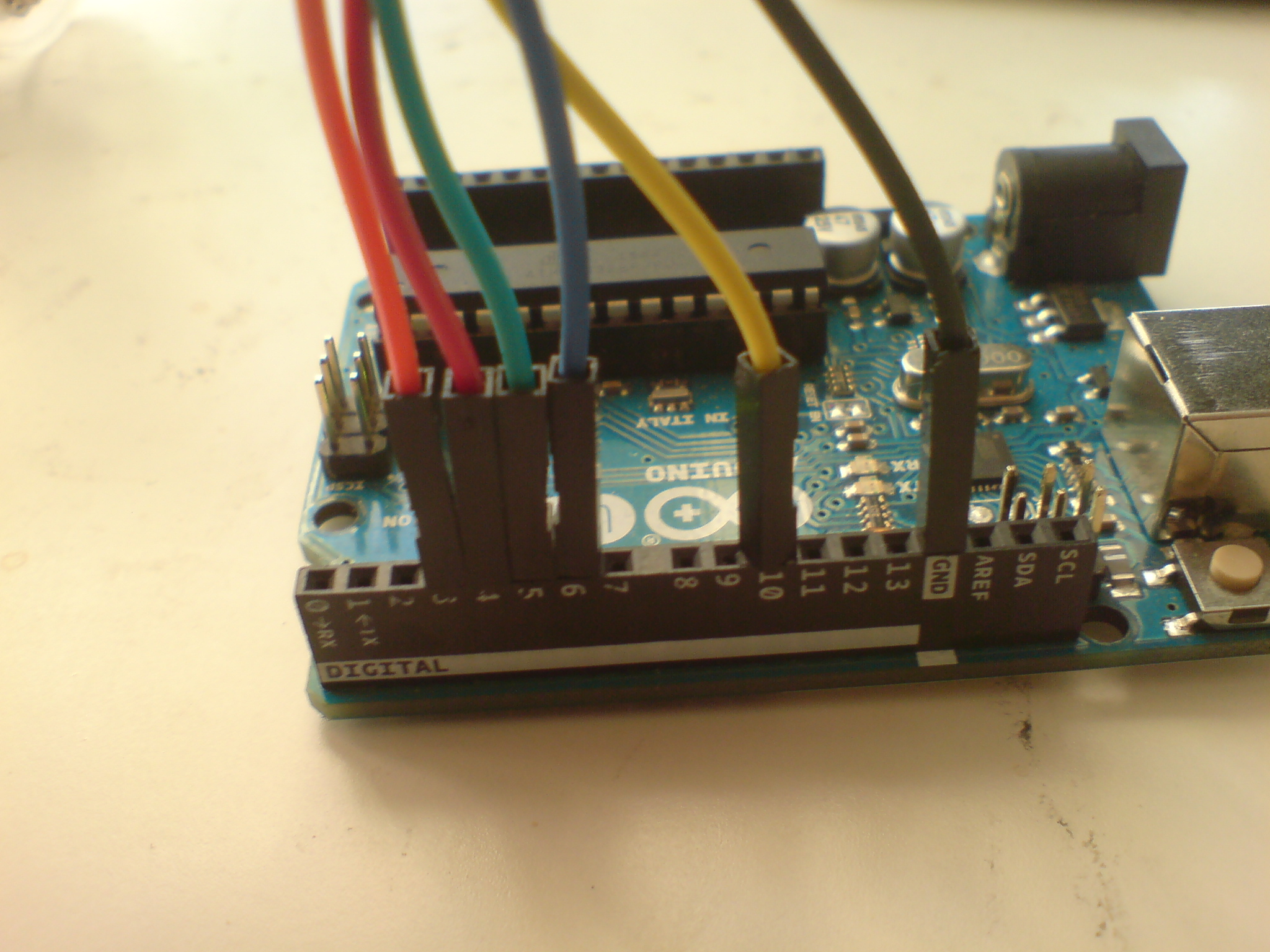
If you have already completed the KVS collector with a resistor side, this step should be piece of cake. Simply connect the wires from the Arduino to their respectively colored wire on the KVS collector's resistored side:
Connection pins on Arduino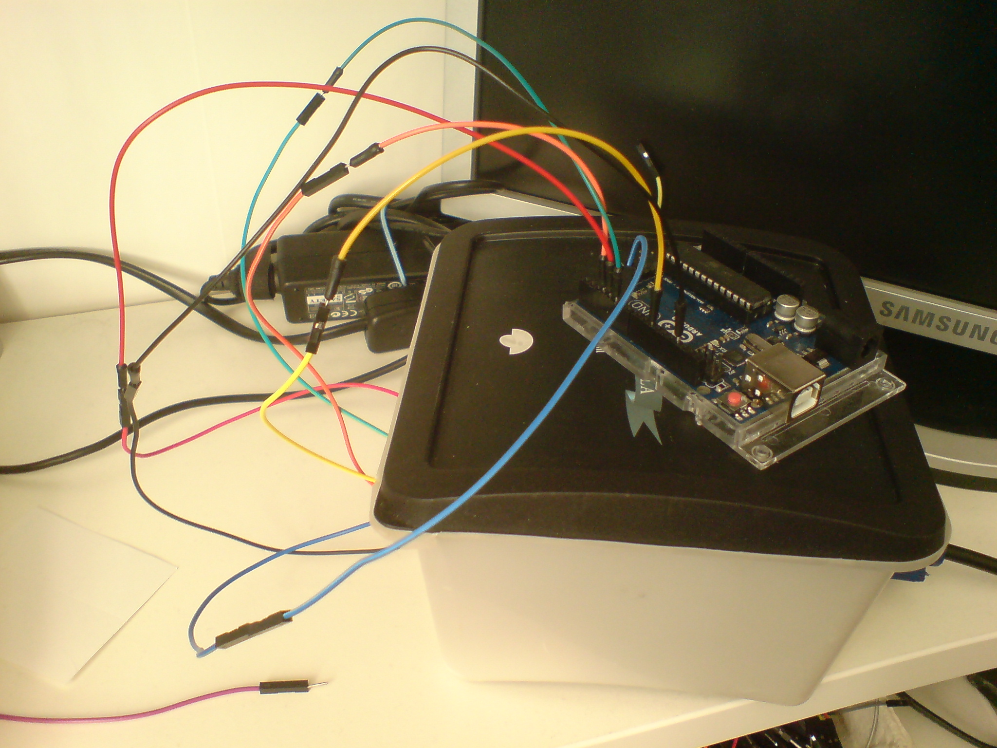
Plug into resistor side of KVS Splicer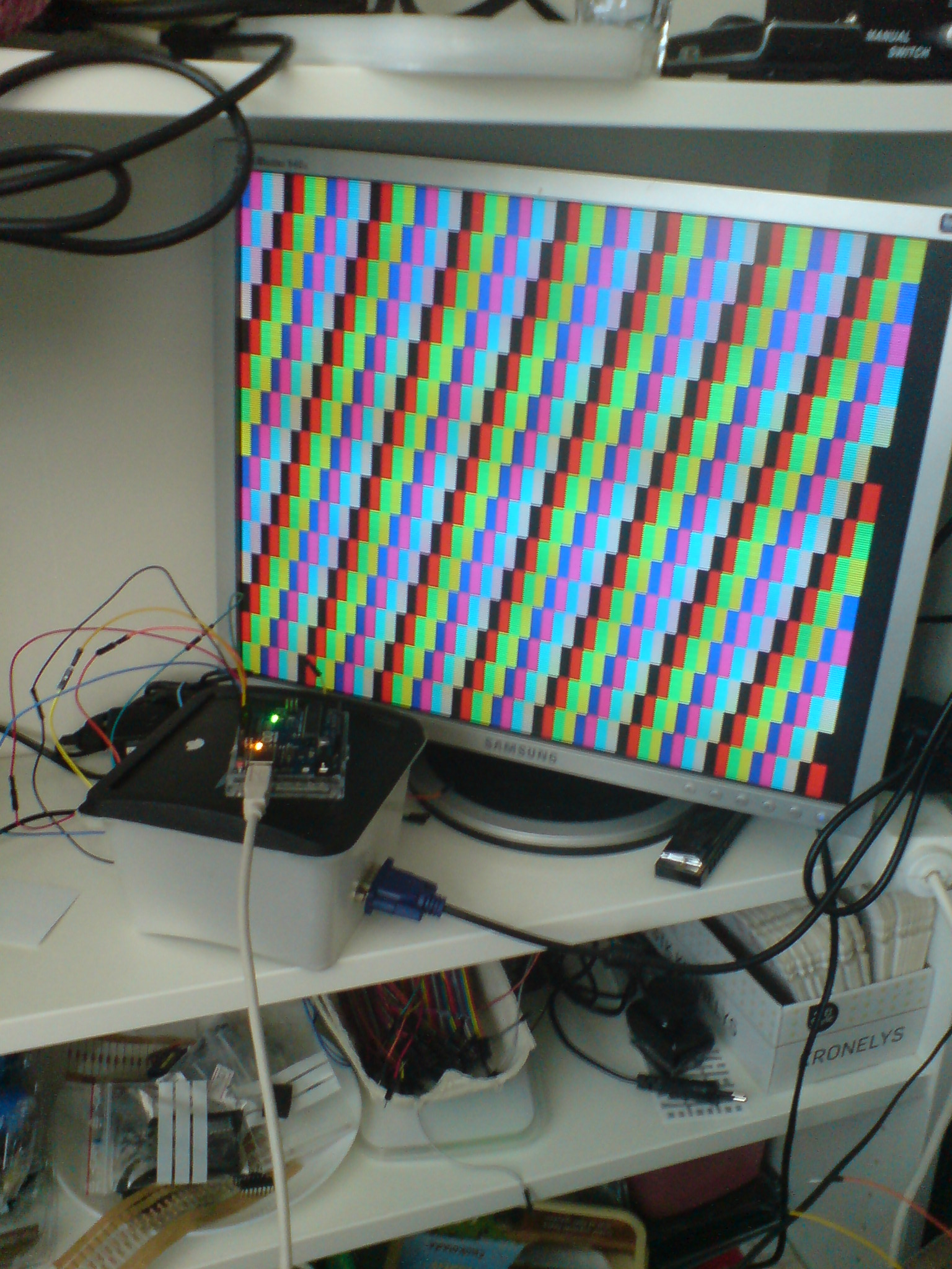
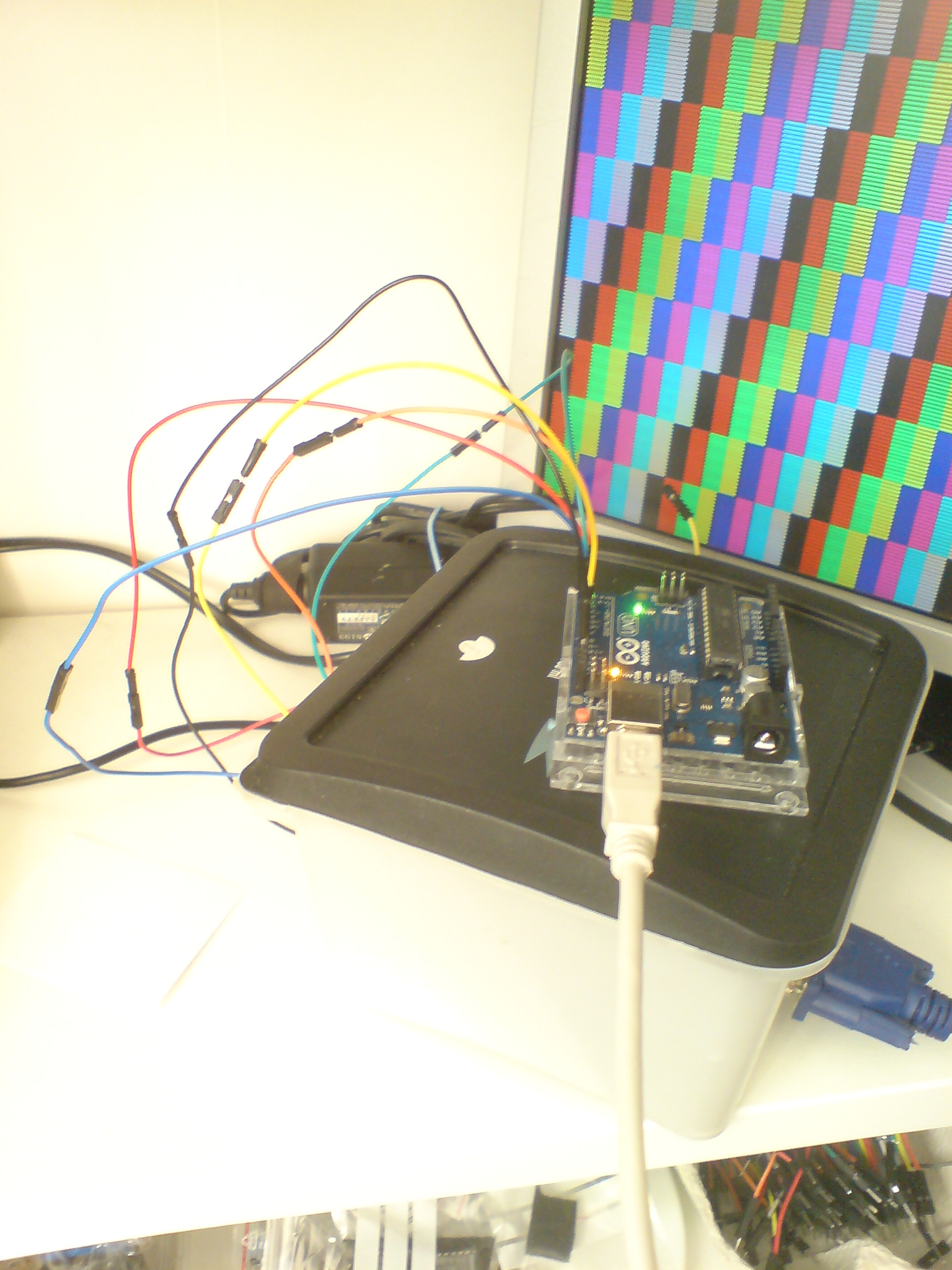
Power on and your monitor should show checkbox pattern
Again, you should experiment with unplugging and shifting the three color cables to see what results it produces and explore how 8 different colors are made by combining just colors of red, green and blue. This process is also known as additive color.
- Pin 3 = h sync (orange)
- Pin 4 = red channel (red)
- Pin 5 = green channel (green)
- Pin 6 = blue channel (blue)
- Pin 10 = v sync (yellow)
- GR = ground (black)
Connection pins on Arduino
Plug into resistor side of KVS Splicer
Power on and your monitor should show checkbox pattern
Theory: Additive Color Process
Combining several colors signals in red, green and blue produce new colors:
red + green = yellow
red + blue = purple
green + blue = cyan
red + green + blue = white/grey
Combining several colors signals in red, green and blue produce new colors:
red + green = yellow
red + blue = purple
green + blue = cyan
red + green + blue = white/grey
Congratulations
In this example, we just copied the code from Gammon in order to make a simple Arduino-based pattern generator. In the next tutorial we will experiment some more with Gammon's code, Arduino programming and additional input components in order to make the KVS Videobox (aka Kaspers Videobox 1) [coming soon].

Filmmaskiner.dk by Kasper Lauritzen is licensed under a Creative Commons Attribution-NonCommercial-ShareAlike 4.0 International License.