KVS Mixer

Filmmaskiner.dk by Kasper Lauritzen is licensed under a Creative Commons Attribution-NonCommercial-ShareAlike 4.0 International License.
Goal
To make the KVS mixer module to mix colors.
You will also learn
To make the KVS mixer module to mix colors.
You will also learn
- How to use variable resistors (potentiometers)
- How to manipulate a color signal through resistance
Try this at your own risk!
I'm sharing these documents in the spirit of DIY and creative commons. It's basically the tutorial I wish I had had when I became interested in making video synthesis. I am, however, not an authorized electrician or engineer, so if you decide trying these things you do so at your own risk and take full responsibility of any harms done to yourself, the hardware in use, our Earth and the universe in general.
I'm sharing these documents in the spirit of DIY and creative commons. It's basically the tutorial I wish I had had when I became interested in making video synthesis. I am, however, not an authorized electrician or engineer, so if you decide trying these things you do so at your own risk and take full responsibility of any harms done to yourself, the hardware in use, our Earth and the universe in general.
You will need
- 1 plastic box for mounting
- Breadboard and additional jumper wires
- For each mixer channel
- 1 potentiometer (linear, mono, 1 or 2 kohm)
- 1 female-to-female jumper wire (with pin header)
- 2 male-to-female jumper wire (with pin header)
- 2 diodes
- Tape and cardboard (optional)
- Tools to cut and make holes
- Sharp knife to detach pin header
- The KVS splitter, Computer with VGA output, VGA cable
- The KVS splicer, Monitor with VGA input, VGA cable
- Plier
Step 1: Making a mixer channel
The mixer channel is based on a potentiometer which dynamically controls the resistance in a color signal. You might have tried adding resistance while you made the KVS splicer. Here we saw that adding a 470 ohm resistor darkens the image on the channel that passes through a resistor.
A potentiometer is also a resistor but a variable resistor, meaning that you can change the resistance that the component makes by turning the knob (e.g. from 0 resistance to 1 kohm).
To try this, plug the female-to-female wire into the left pin of the potentiometer, and plug the male-to-female wire into the middle pin of the potentiometer. The potentiometer can now regulate the resistance on this connection. While the KVS splitter and the KVS splicer are connected on wires h, v and ground, connect one color channel of the KVS splitter to the female-to-female side of the potentiometer, and the male-to-female side into the KVS splicer. Turn the knob and see how you can brighten and darken the color through this operation.
Practical note: What kind of potentiometers are there?
Resistance - 1 kohm...?
Linear vs. log
Mono vs. dual
Resistance - 1 kohm...?
Linear vs. log
Mono vs. dual
Step 2: Mounting
Once you've tested each of the mixer channels you want, you're ready to mount it into a box.
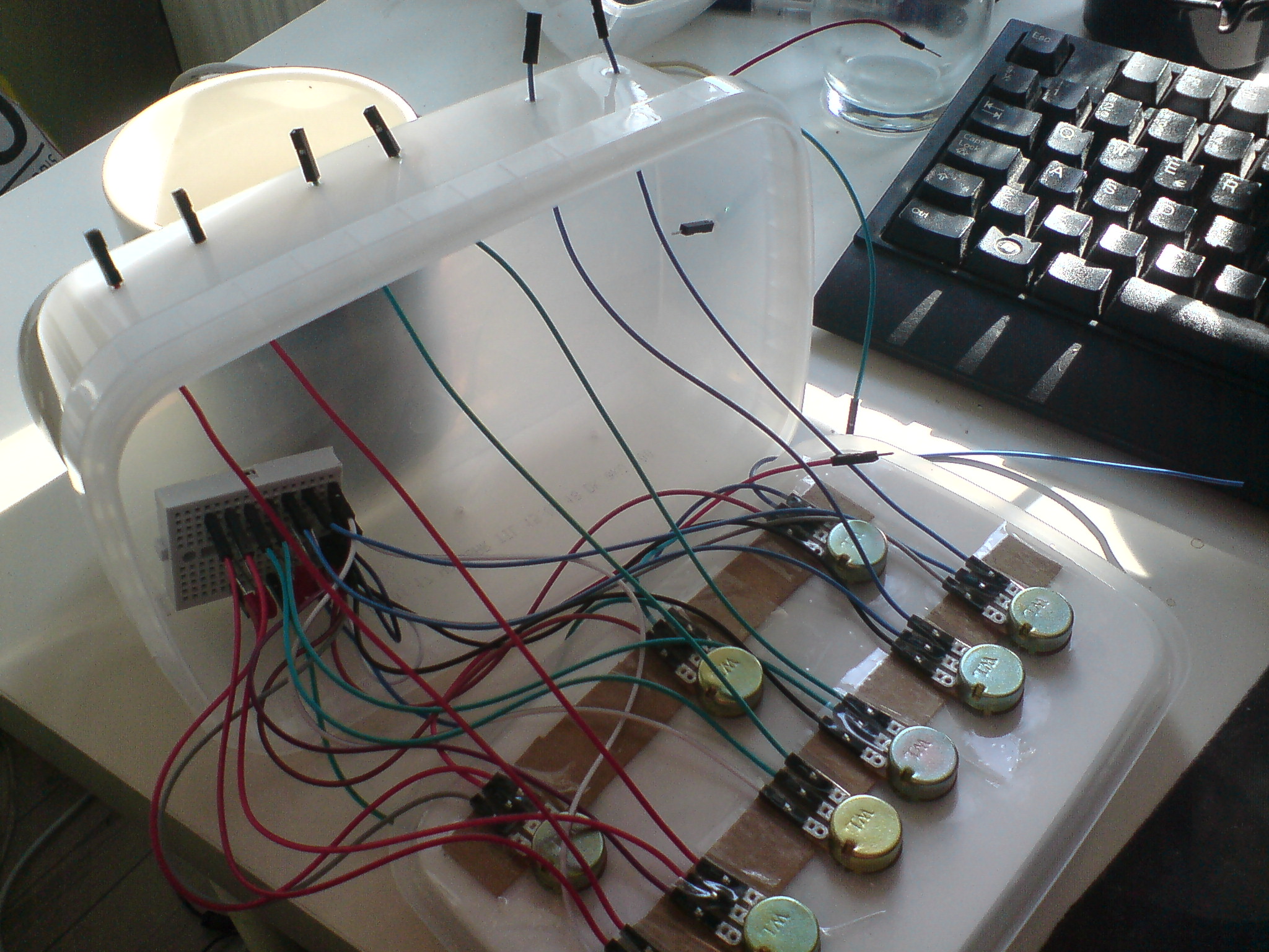
First, I make holes in the bottom of the plastic box for the potentiometer using a screwdriver. After that, unscrew the shaft, stick the potentiometer through the hole, and mount it with the shaft again.
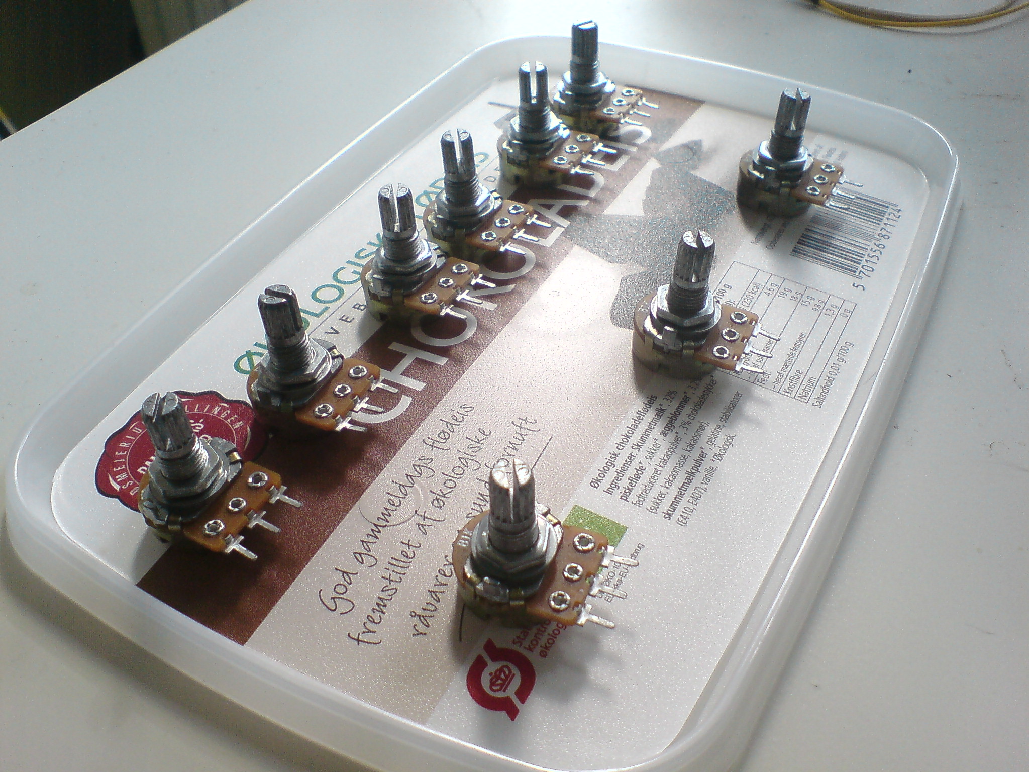
Layout of my mounting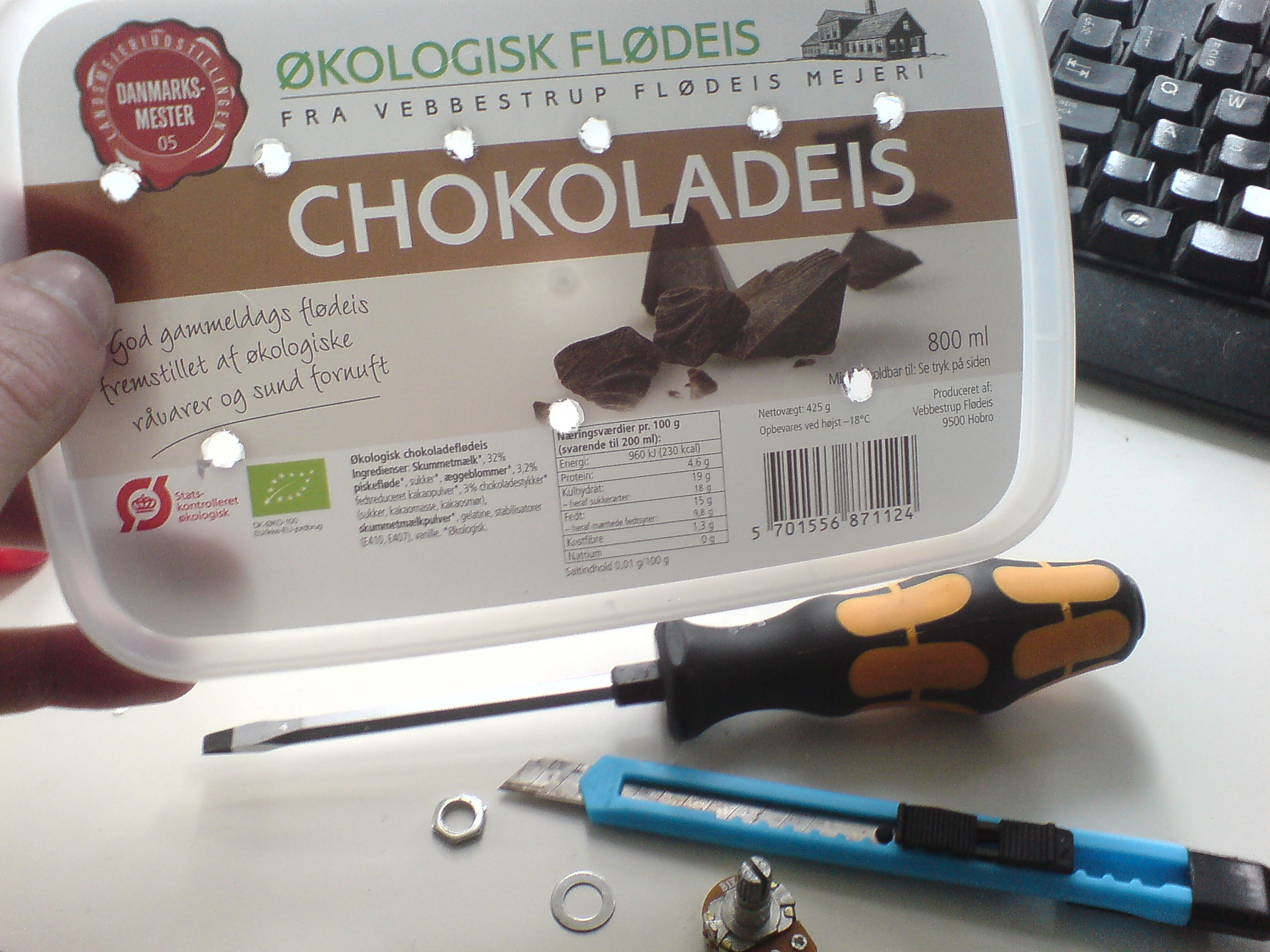
Holes in the lid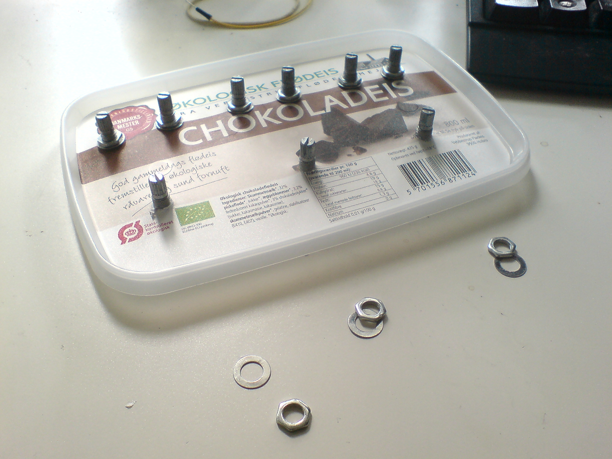
Use the shaft to mount in holes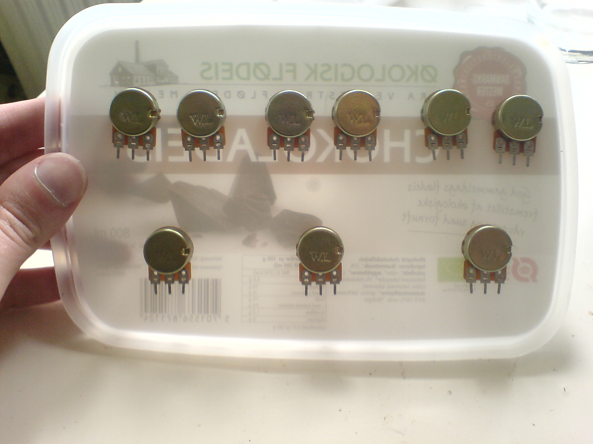
Pots mounted with pins in the same direction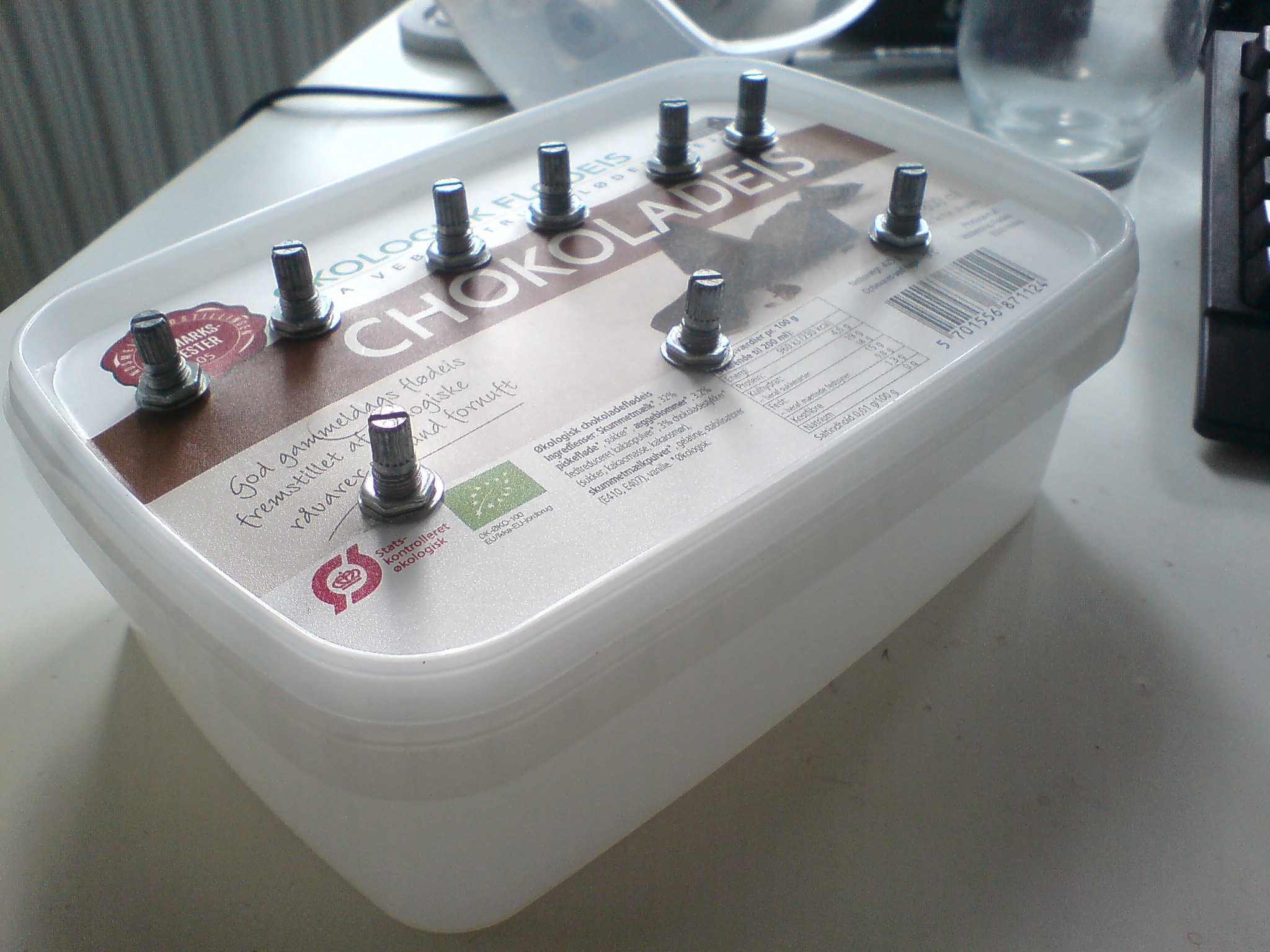
Result
 Practical note: How to mount the potentiometer?
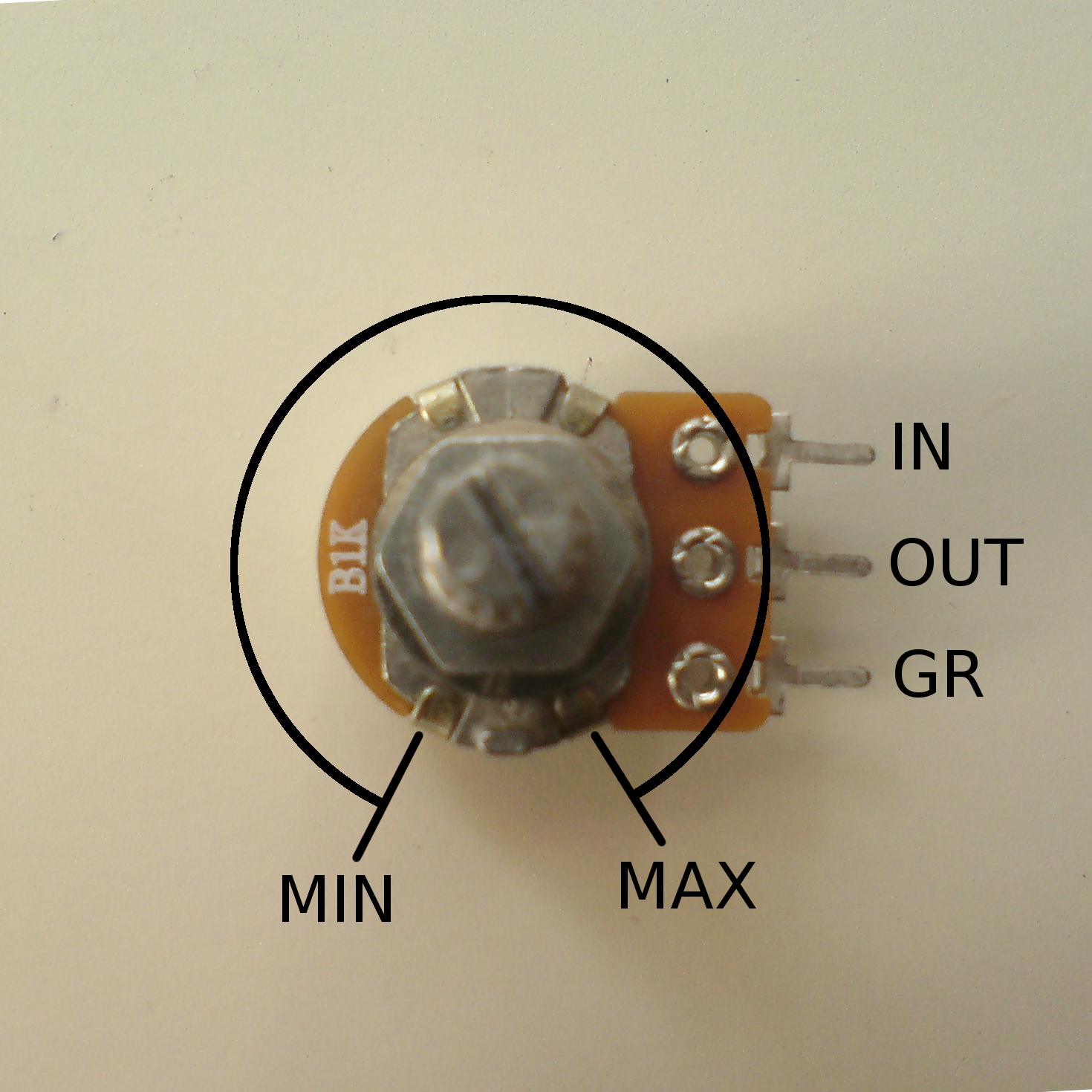
Before you mount the potentiometer make note of where the minimum and maximum positions are.
The basic idea is to put a ground input and the signal input on either side of the potmeter with the output in the middle. This way, if the knob is turned completely to the minimum position, the output will be ground. If the knob is turned completely to the maximum, the output will be the input. Everything in between varies the balance between ground and signal, meaning that you can "fade" the signal from complete color to (ideally) total black.
On my potmeter, the minimum and maximum are placed at a right angle to the pins, so I mount it sideways.
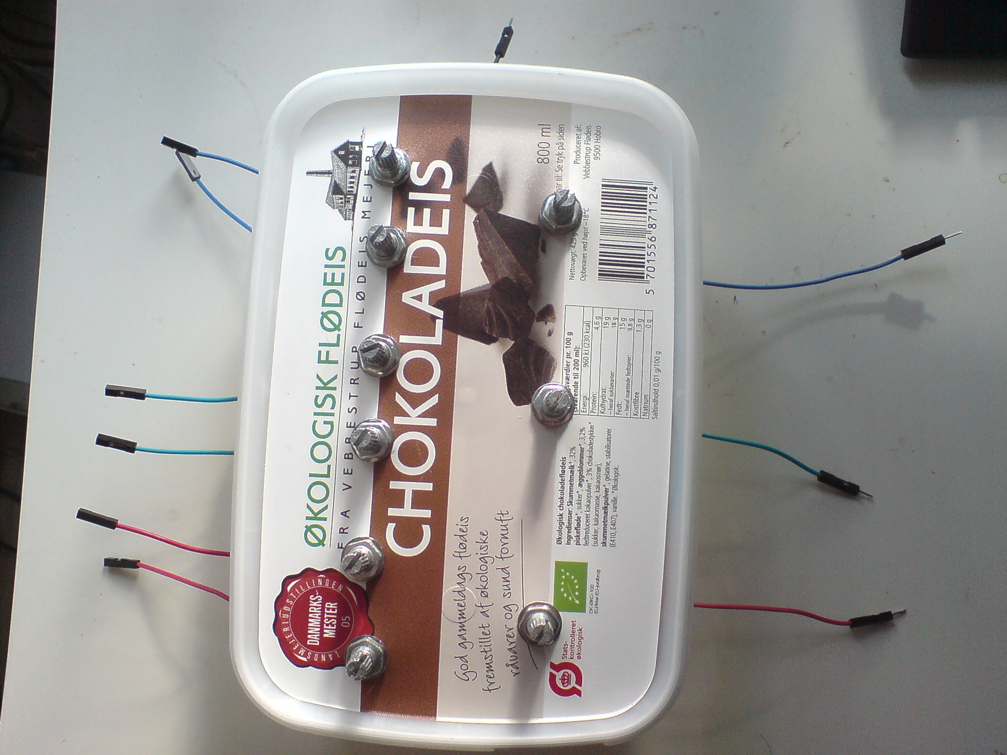
We will use a ground signal as the input of the other potentiometer terminal, so that we can lower the output even better. In order to do this, we need a breadboard setup. First we connect the wires to each of the three terminals of all the potentiometers. Looking at them from behind (as opposed to knob site), the far right are for ground (use male-to-female wire), the middle is to output (use male-to-female wires), and the left is for input (use female-to-female wires - they go out of the box). You can use cardboard to hold the wires in the potentiometer, by cutting a support to each potentiometer, and then tape it to the bottom and tape the wires to the cardboard for support.
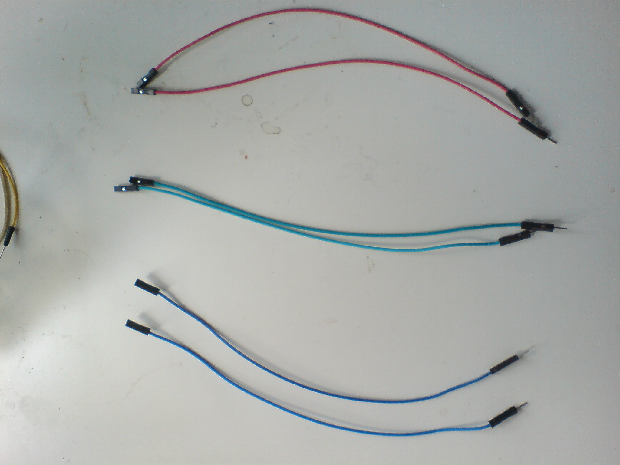
Use male-to-female for connecting pots to breadboard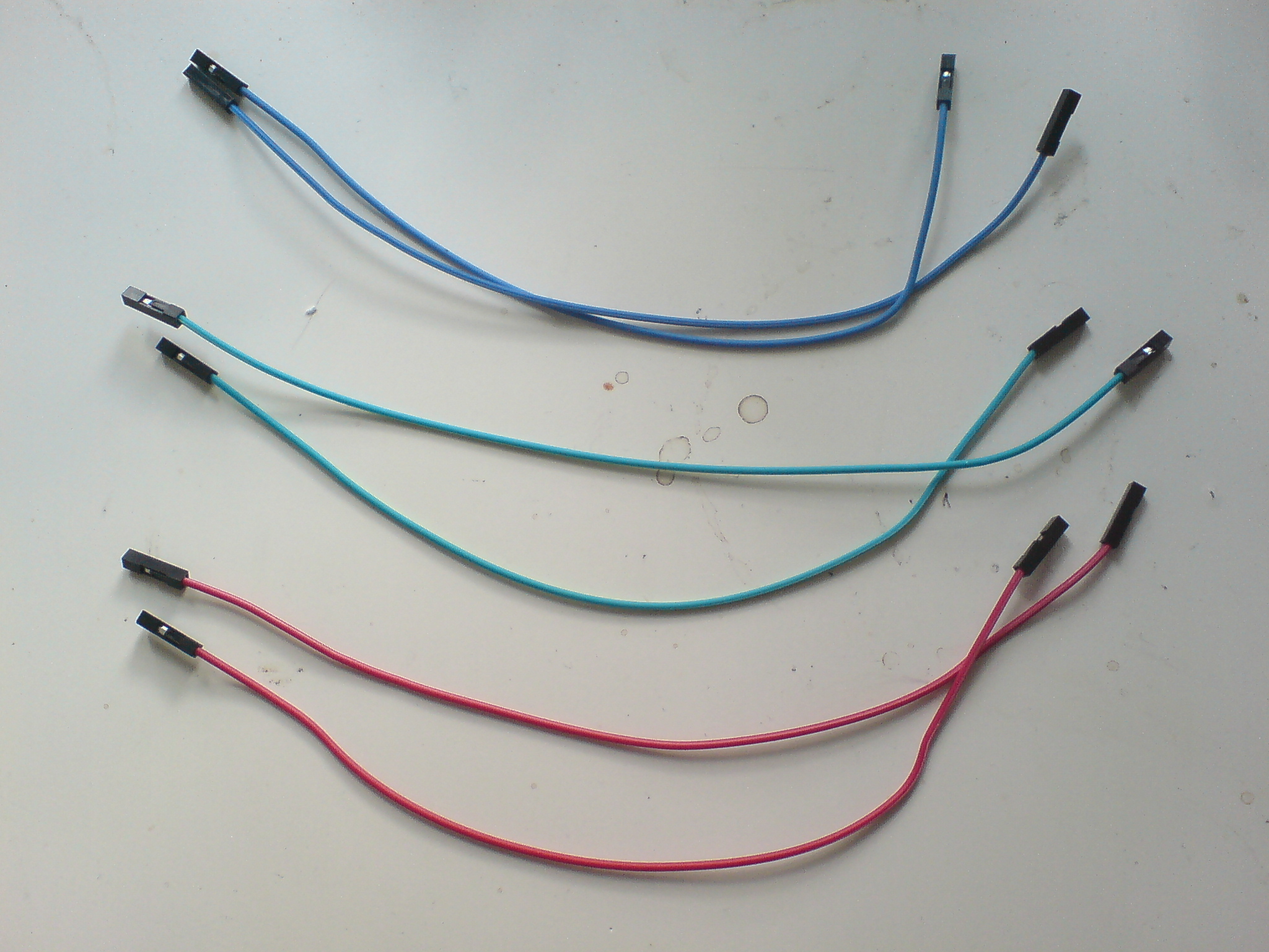
Use female-to-female for incoming signal to pot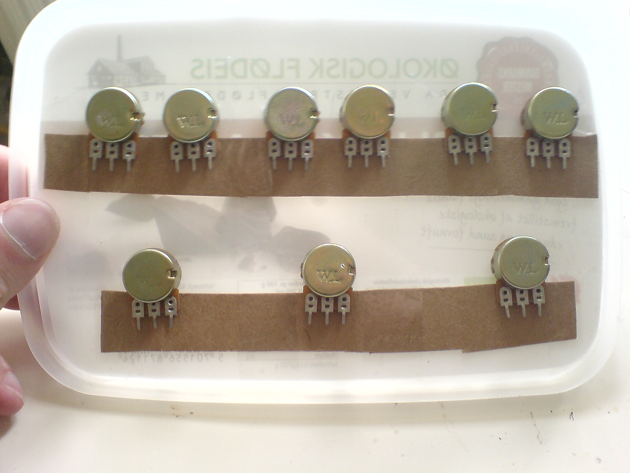
Tape a cardboard to the lid to hold the wires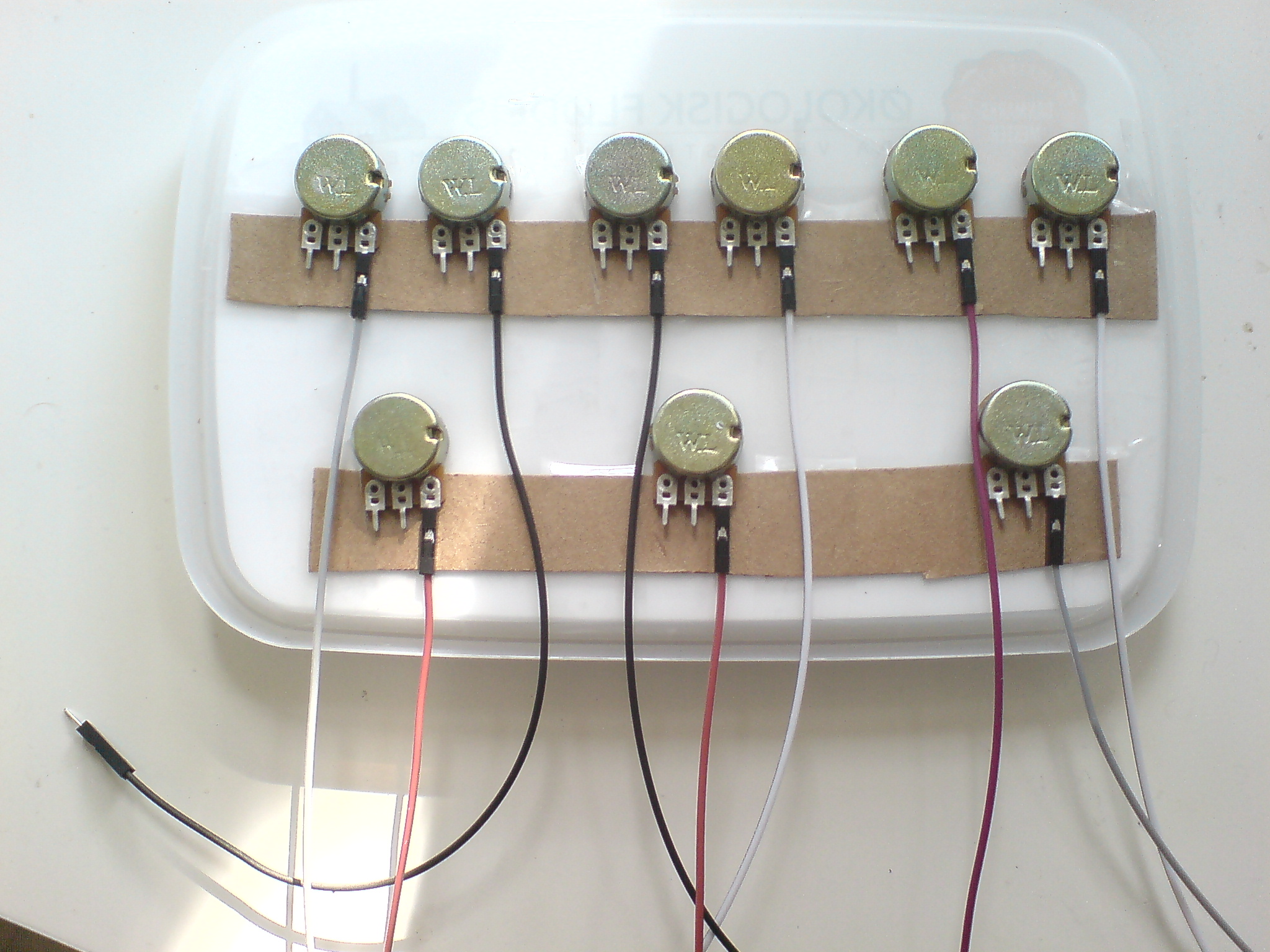
Connect ground wires to terminals (male-to-female)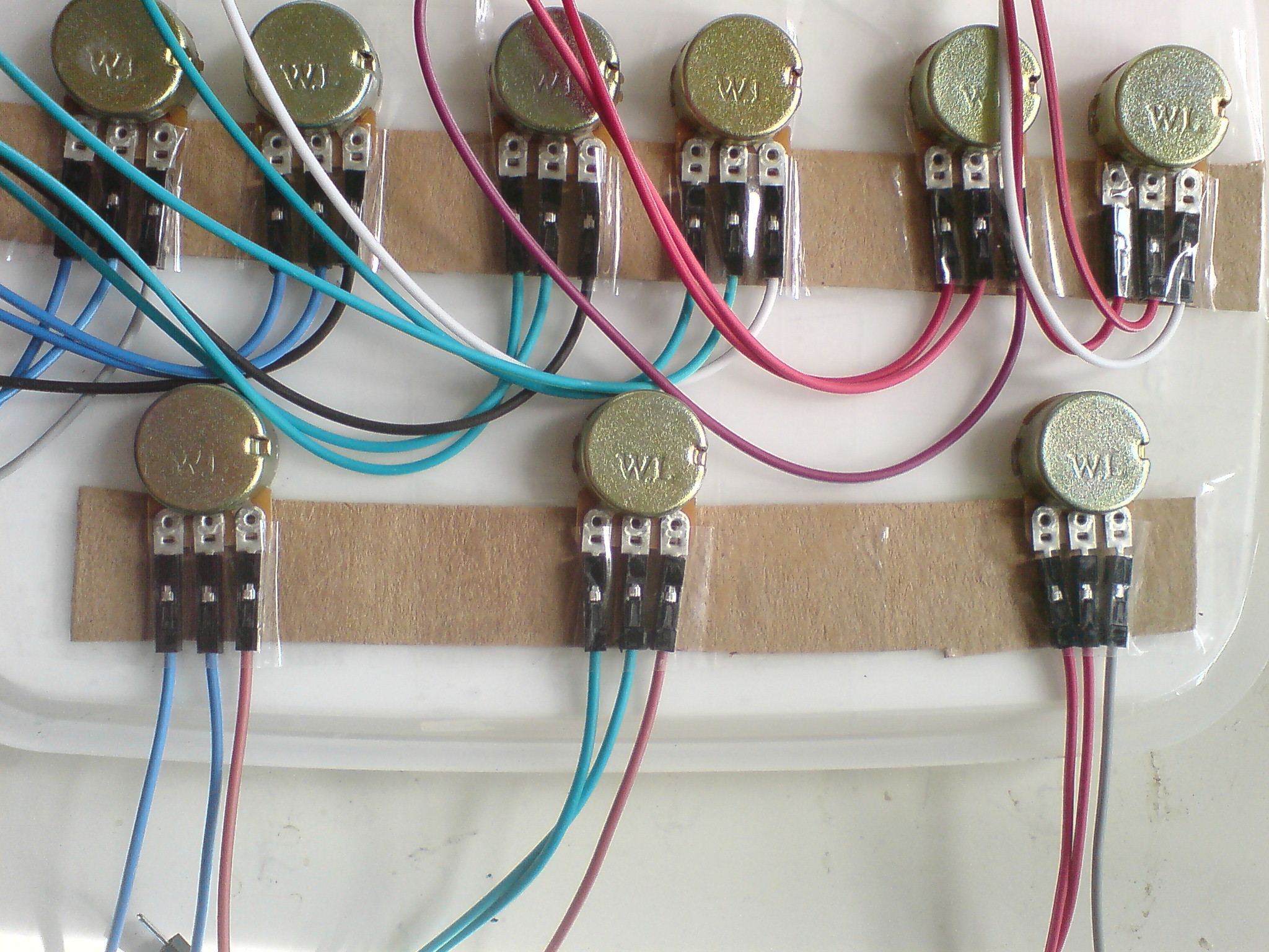
Connect signal wires to terminals
First, I make holes in the bottom of the plastic box for the potentiometer using a screwdriver. After that, unscrew the shaft, stick the potentiometer through the hole, and mount it with the shaft again.
Layout of my mounting
Holes in the lid
Use the shaft to mount in holes
Pots mounted with pins in the same direction
Result
Before you mount the potentiometer make note of where the minimum and maximum positions are.
The basic idea is to put a ground input and the signal input on either side of the potmeter with the output in the middle. This way, if the knob is turned completely to the minimum position, the output will be ground. If the knob is turned completely to the maximum, the output will be the input. Everything in between varies the balance between ground and signal, meaning that you can "fade" the signal from complete color to (ideally) total black.
On my potmeter, the minimum and maximum are placed at a right angle to the pins, so I mount it sideways.
Use male-to-female for connecting pots to breadboard
Use female-to-female for incoming signal to pot
Tape a cardboard to the lid to hold the wires
Connect ground wires to terminals (male-to-female)
Connect signal wires to terminals
Step 3: Breadboard setup
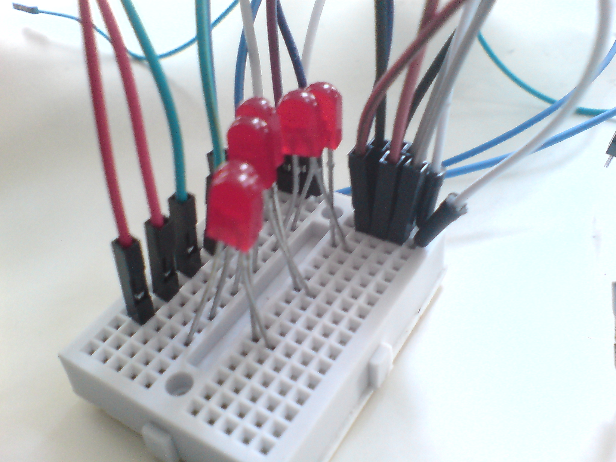
In order to prevent "back fire" in the circuit, we will use two diodes for each mixer, where we connect the two incoming pots to the outgoing pot, in order to make the current run from in to out. Here I have used LEDs (light-emitting diodes) because I had those at hand, but you should use normal diodes, so that the power is not consumed by the lights.
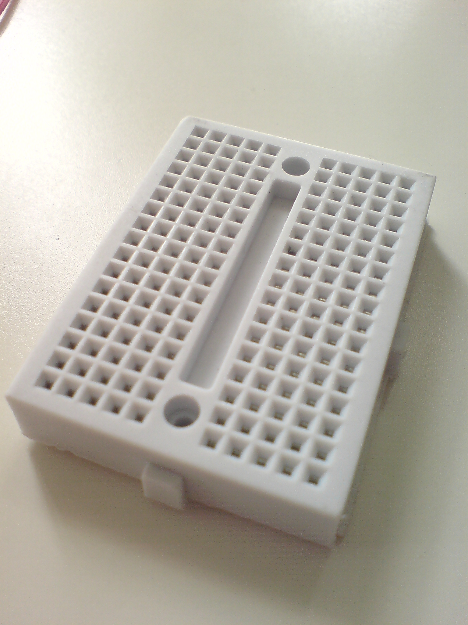
You will need a breadboard...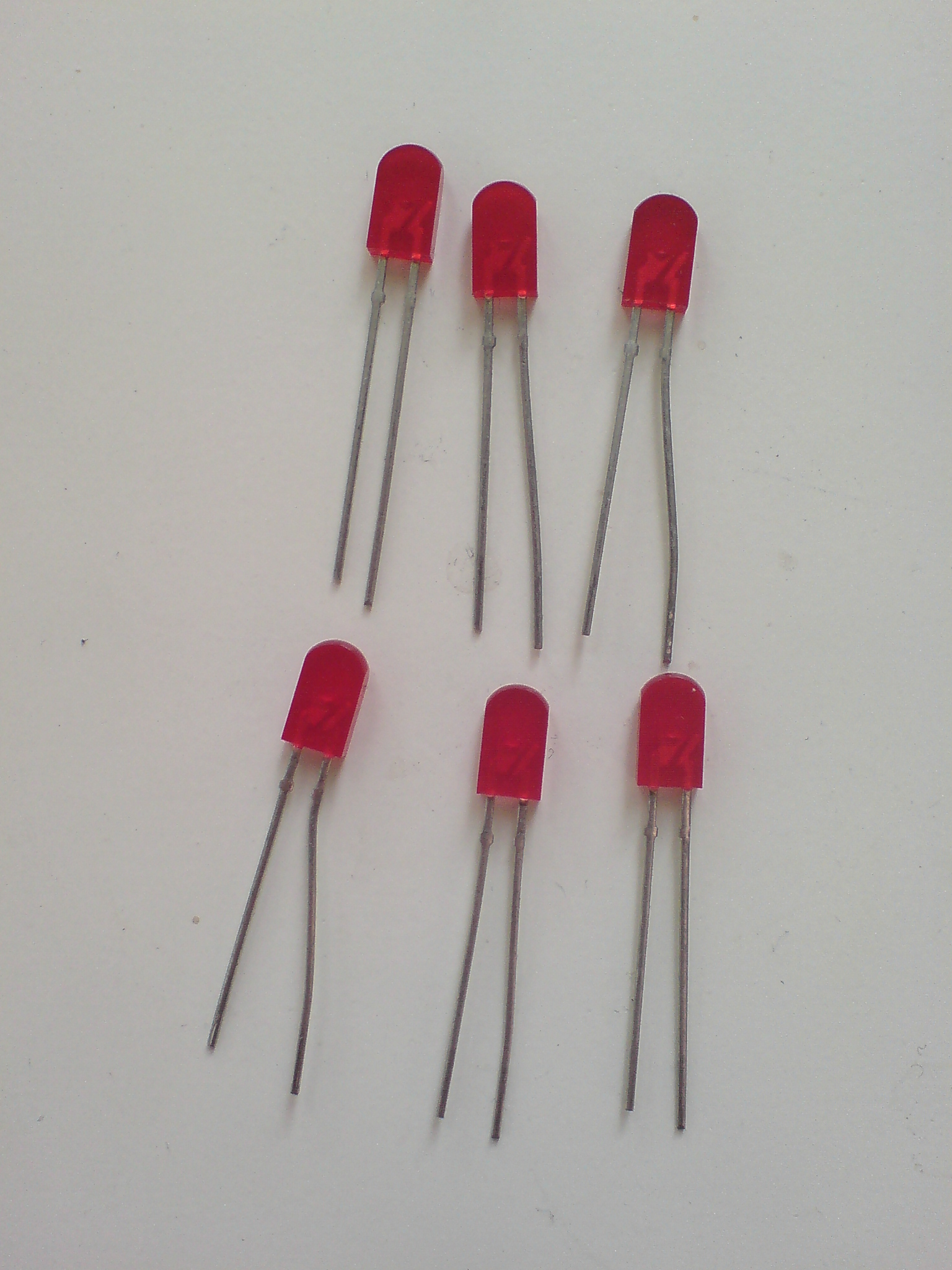
... and some diodes (here light-emitting diodes)
Connect the diodes on the breadboard, so that the power pins (the long leg) have one row on the breadboard each and the ground pins (the short leg) cross and go to the same row. By connecting the output of the two incoming pots to one row each, and the wire, leading to the outgoing pot's input, to the crossed row, the two inputs will be combined in the next pot (if both are active) and their sum will be controlled by this potentiometer as a master control.
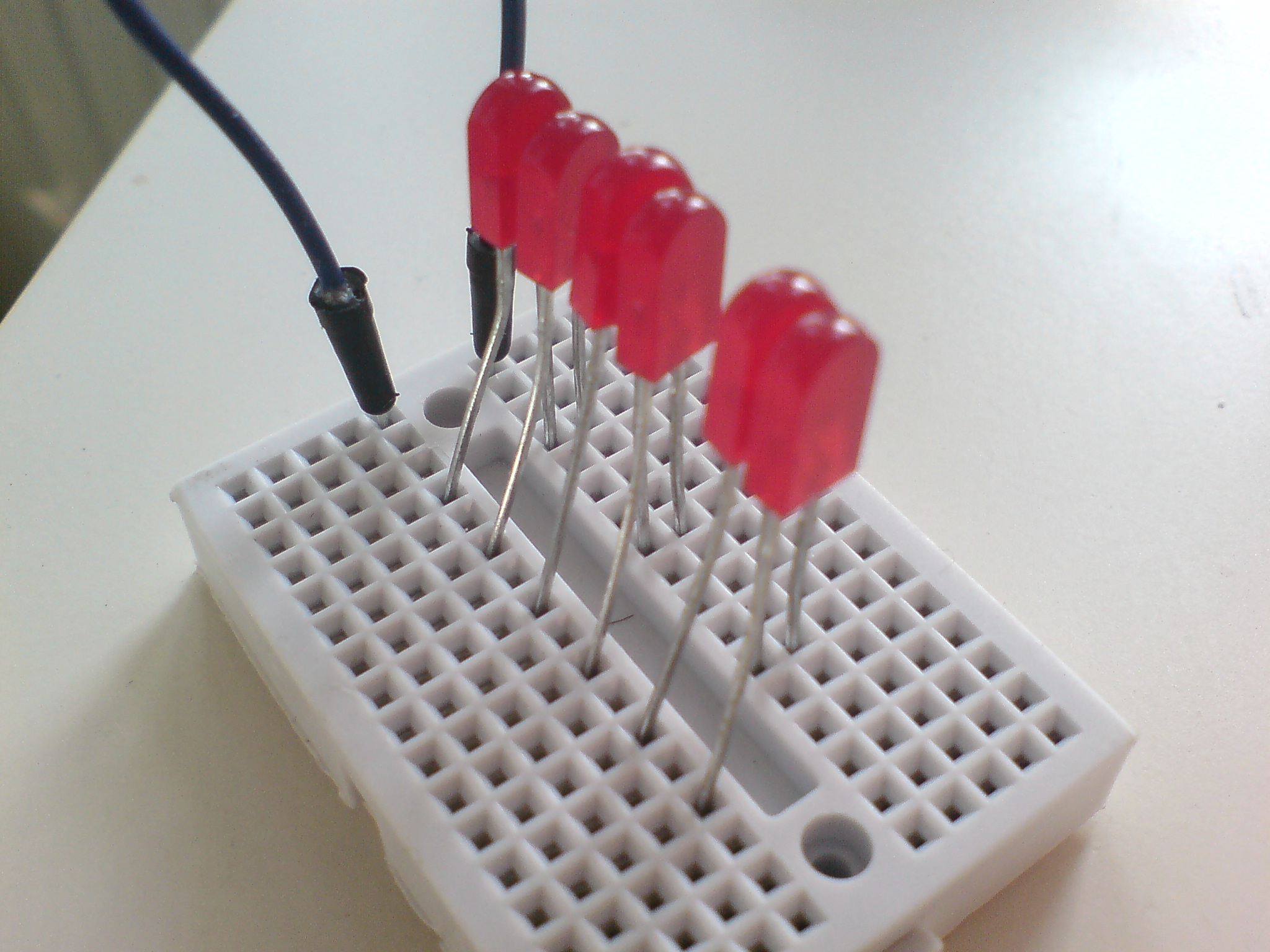
Setup the diodes with short legs crossing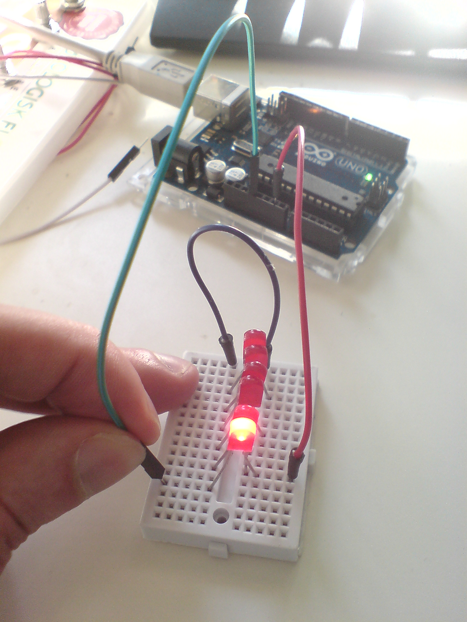
You might want to test if they work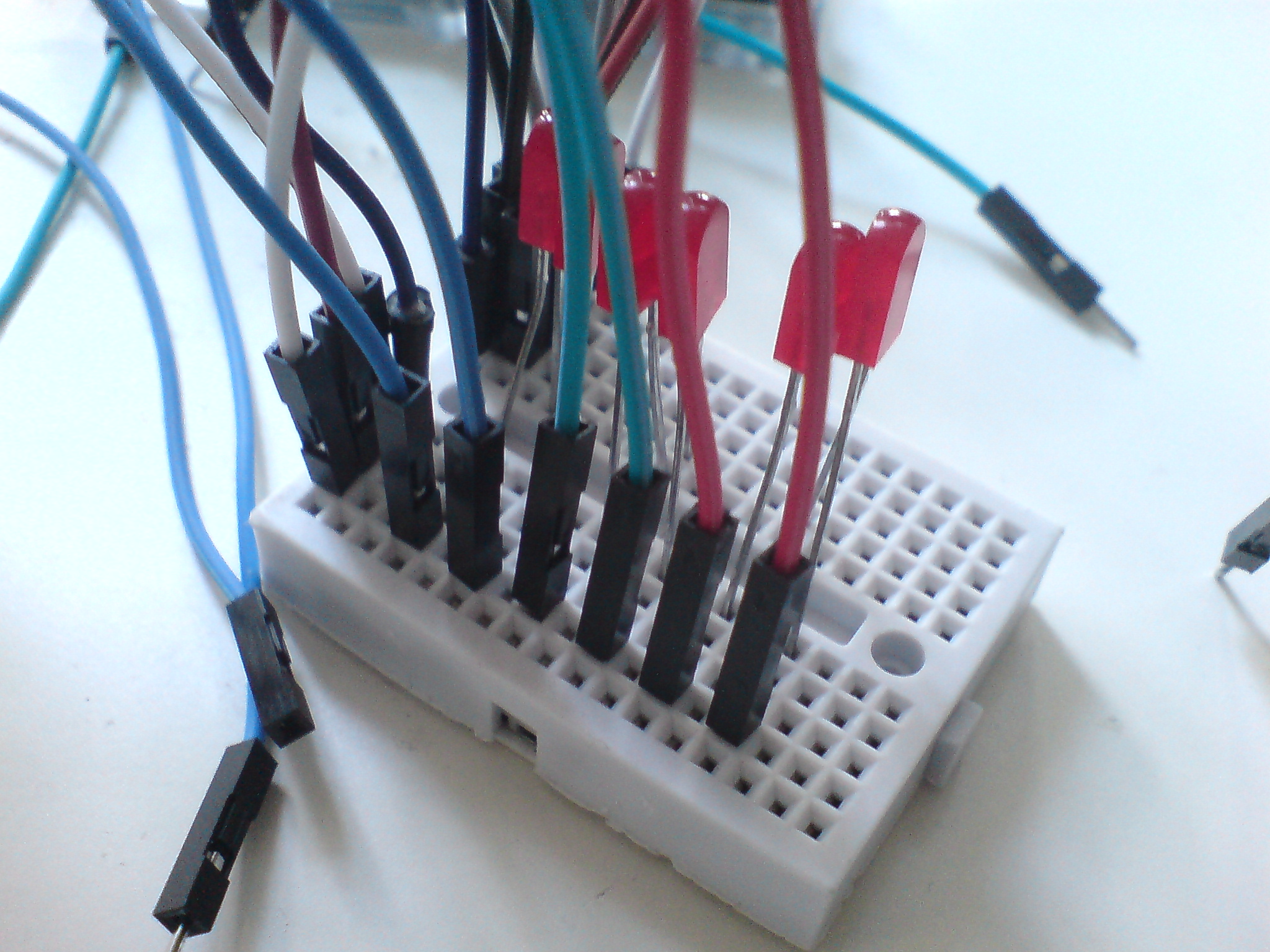
Connect the outputs to non-crossed site
Finally, you should also connect the ground terminal to the breadboard and use one male-to-male wire that goes out of the box to provide ground signal.
Connect the ground terminal to breadboard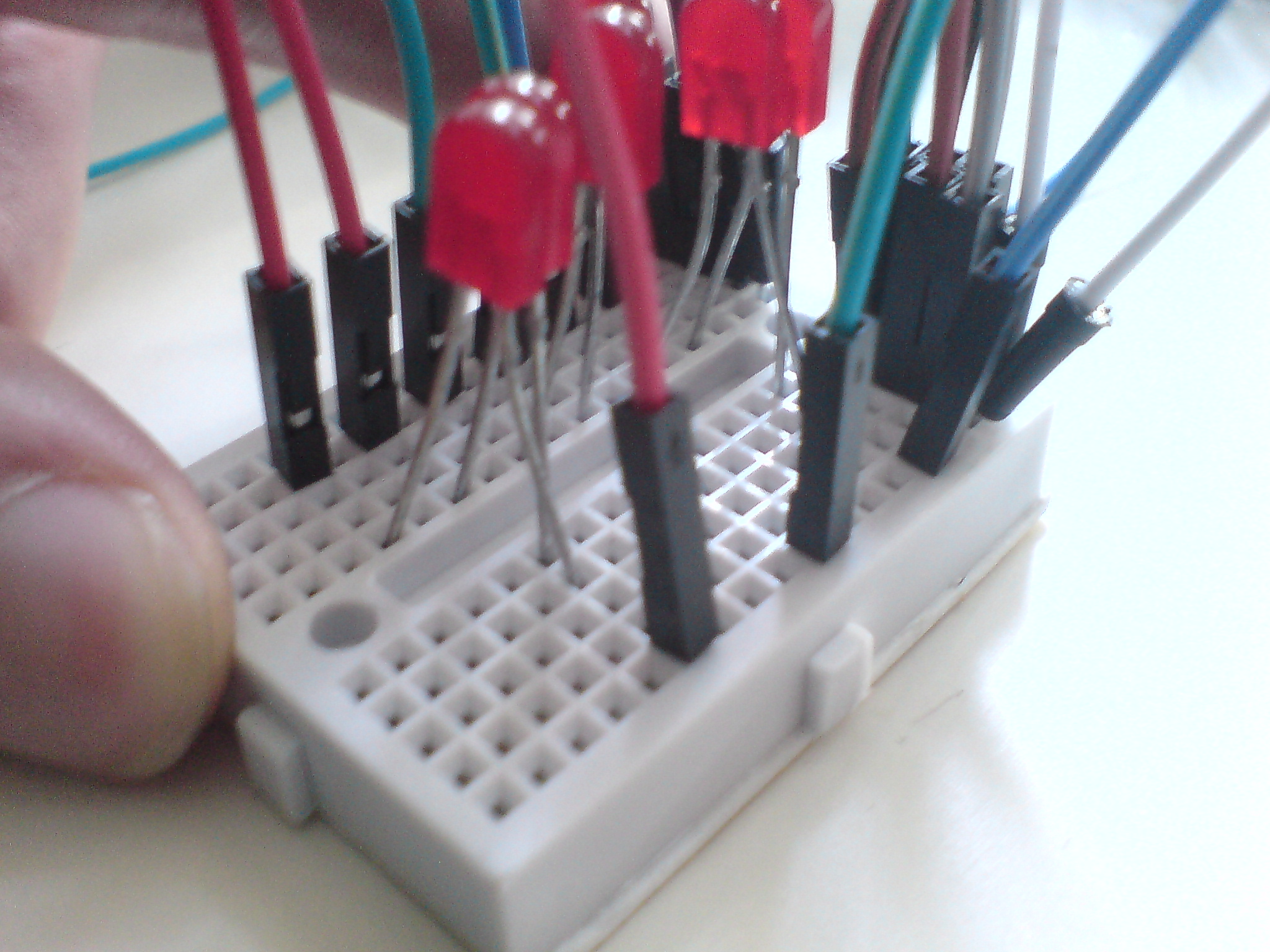
Connect the crossed sites to the master pot
You will need a breadboard...
... and some diodes (here light-emitting diodes)
Setup the diodes with short legs crossing
You might want to test if they work
Connect the outputs to non-crossed site
Connect the ground terminal to breadboard
Connect the crossed sites to the master pot
Step 4: Final touch
Last but not least, you need to make wire holes in the sides of the box where the jumper wires can go through - I keep the female-to-female wires on the left and their corresponding male-to-female wires on the right in the same order. *Detach the pin header* of the wires, stick them through the small holes, and reattach the pin headers.
First connect the female wires (from slave) to one site of box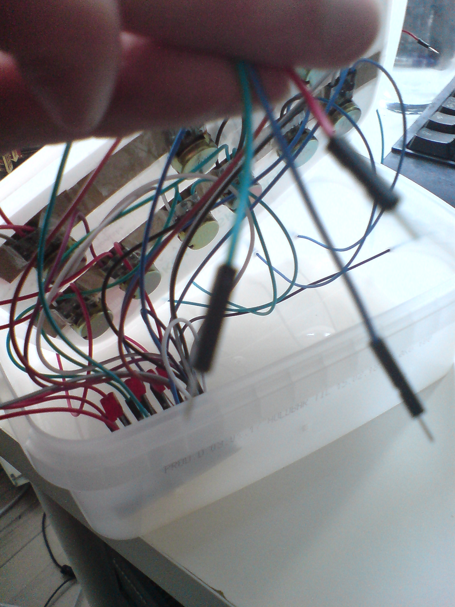
Then make holes for the male wires (from master)...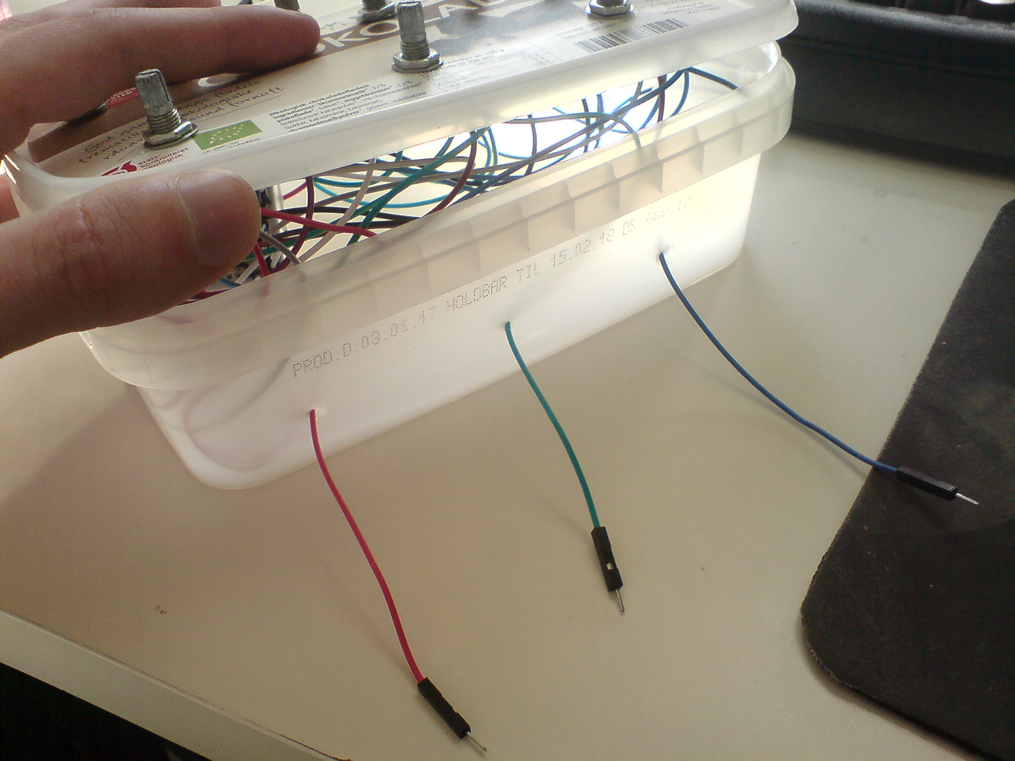
... and mount on other site of the box
First connect the female wires (from slave) to one site of box
Then make holes for the male wires (from master)...
... and mount on other site of the box
Congratulations
That wasn't hard, was it?
The KVS mixer will come in handy as we move on, and begin to combine signals from different sources and techniques. So keep it ready while we move on to the next tutorial about the KVS Arduino module.
The KVS mixer will come in handy as we move on, and begin to combine signals from different sources and techniques. So keep it ready while we move on to the next tutorial about the KVS Arduino module.
Filmmaskiner.dk by Kasper Lauritzen is licensed under a Creative Commons Attribution-NonCommercial-ShareAlike 4.0 International License.