KVS Oscillator aka Kazz Noizer


Filmmaskiner.dk by Kasper Lauritzen is licensed under a Creative Commons Attribution-NonCommercial-ShareAlike 4.0 International License.
Goal
To make the KVS Oscillator aka Kazz Noizer.
To make the KVS Oscillator aka Kazz Noizer.
Try this at your own risk!
I'm sharing these documents in the spirit of DIY and creative commons. It's basically the tutorial I wish I had had when I became interested in making video synthesis. I am, however, not an authorized electrician or engineer, so if you decide trying these things you do so at your own risk and take full responsibility of any harms done to yourself, the hardware in use, our Earth and the universe in general.
I'm sharing these documents in the spirit of DIY and creative commons. It's basically the tutorial I wish I had had when I became interested in making video synthesis. I am, however, not an authorized electrician or engineer, so if you decide trying these things you do so at your own risk and take full responsibility of any harms done to yourself, the hardware in use, our Earth and the universe in general.
You will need
- SN74LS629N chip (dual voltage-controlled oscillators)
- Breadboard (mini)
- 13 * male-to-male
- 3 * male-to-female
- 2 * 100 nf capacitor (ceramic)
- Female Jack socket (3.5 mm) stereo
- 5 volt DC power source (e.g. Arduino UNO or battery - see "portable version")
- Alligator clips wires
- Positive voltage regulator (5 volt, 1.5 A) - UA7805C
- Battery clips
- On/off button
- Box for mounting
Step 1: Making the circuit
KVS Oscillator aka Kazz Noizer is a simple voltage-controlled oscillator (or wave generator) which can create audio and/or visuals by adding resistance to the low-voltage circuit.
The KVS Oscillator aka Kazz Noizer is an easy application of the SN74LS629N. The LS629 contains two oscillators running on the same power source but with seperate input for frequency and range control. If you look in the datasheet you can see the different functions of each pin.
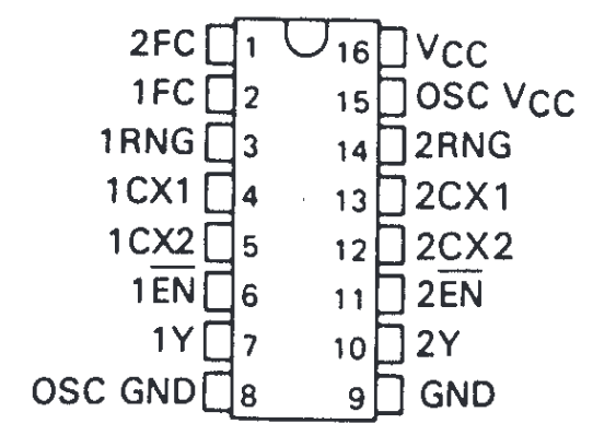
Pin information from datasheet
Circuit diagram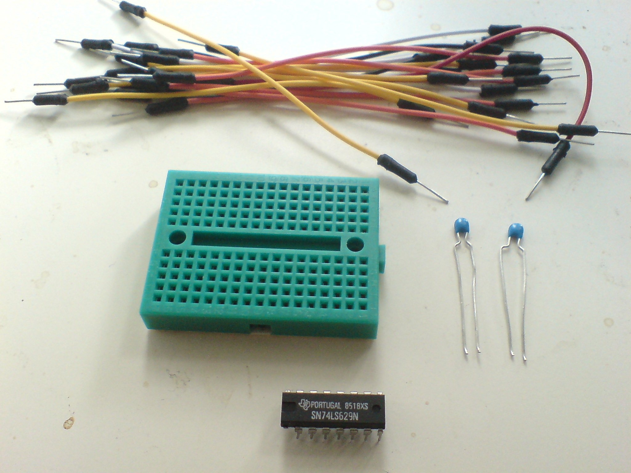
Materials needed
First, we will connect the power and ground pins. Pin 15 and 16 provides power for the oscillators and the chip itself, respectively, and pins 8 and 9 are ground for oscillator and chip. Furthermore, the two "en" pins (pins 6 and 11) need to be grounded.
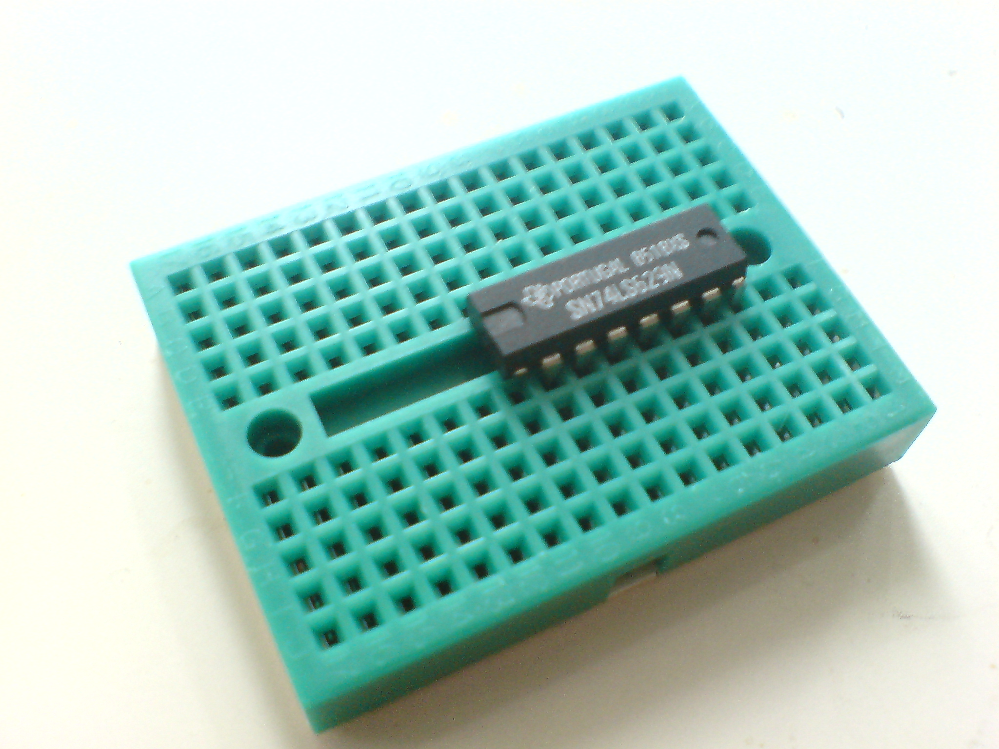
Chip in breadboard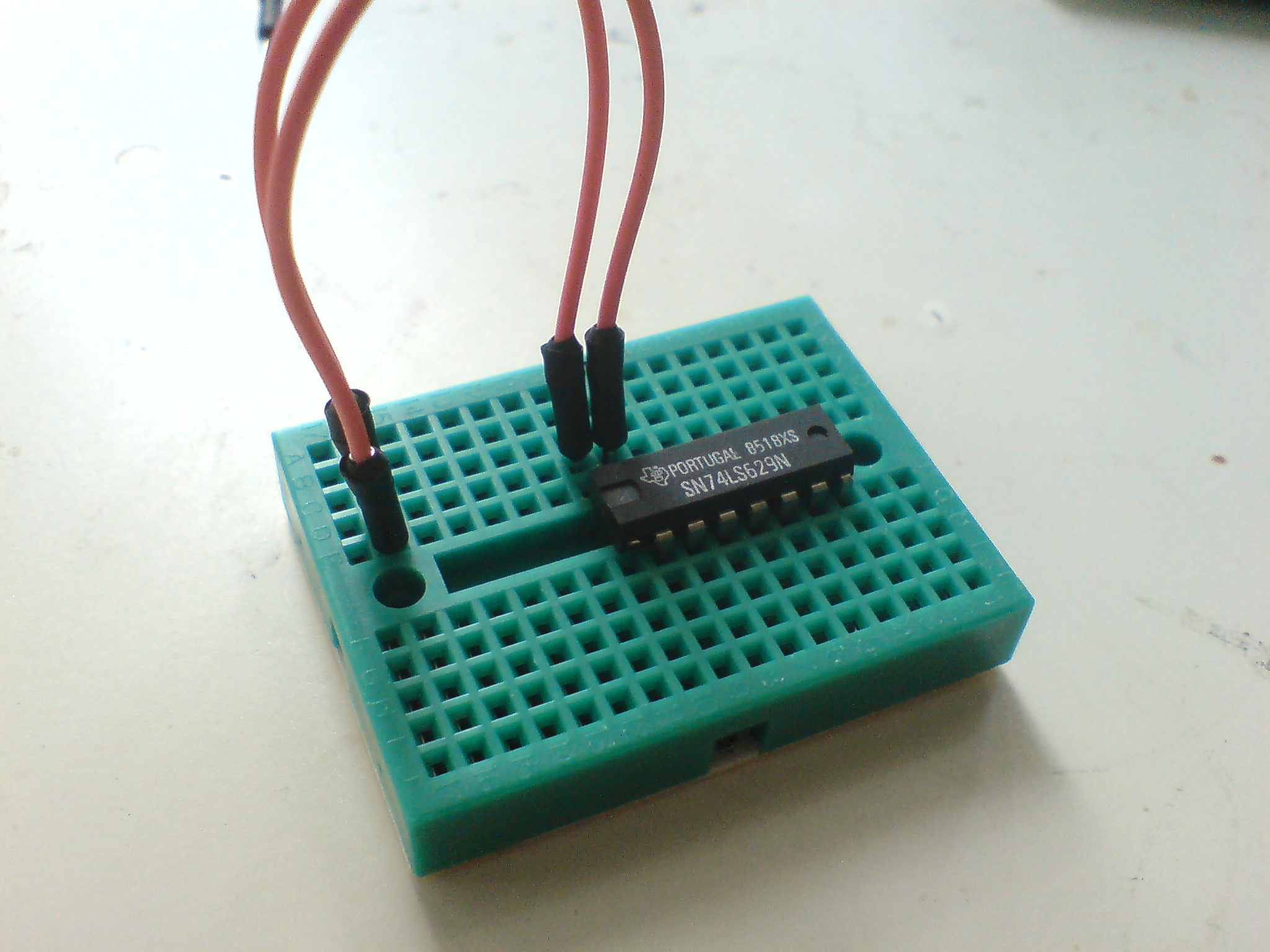
Connecting to power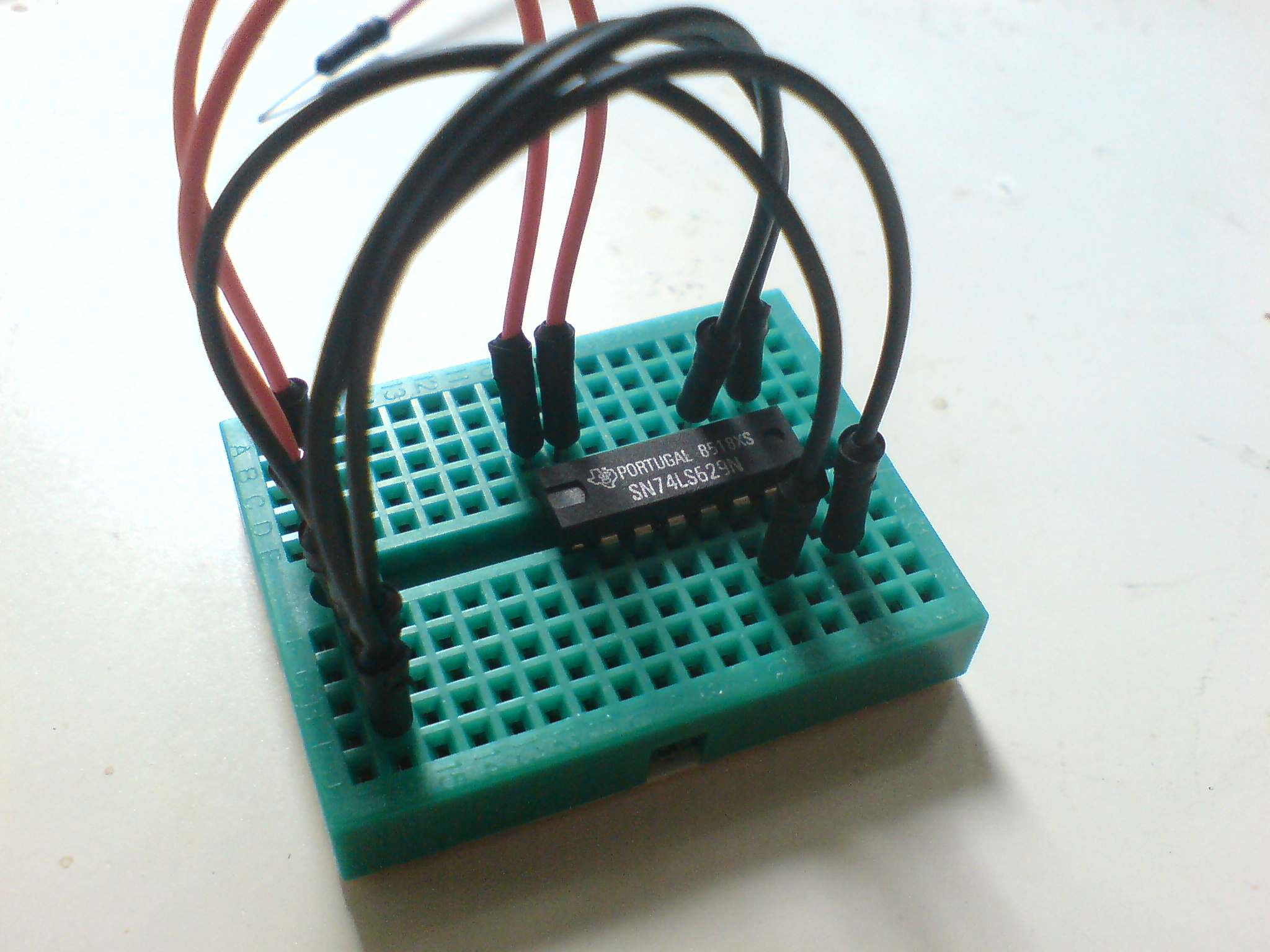
Connecting to ground
Next, we add the 100 nf capacitors that makes the oscillation. These should be added between the two CX pins for each oscillator, ie. one between pins 12 and 13, and the other between pins 4 and 5.
Then we put one male-to-female wire to each of the output pins (pin 7 for oscillator #1 and pin 10 for oscillator #2). We'll connect the two female ends to the jack socket in a second. I've chosen a yellow wire for oscillator #1 and an orange wire for oscillator #2 to keep track of the oscillators, but this is not essential.
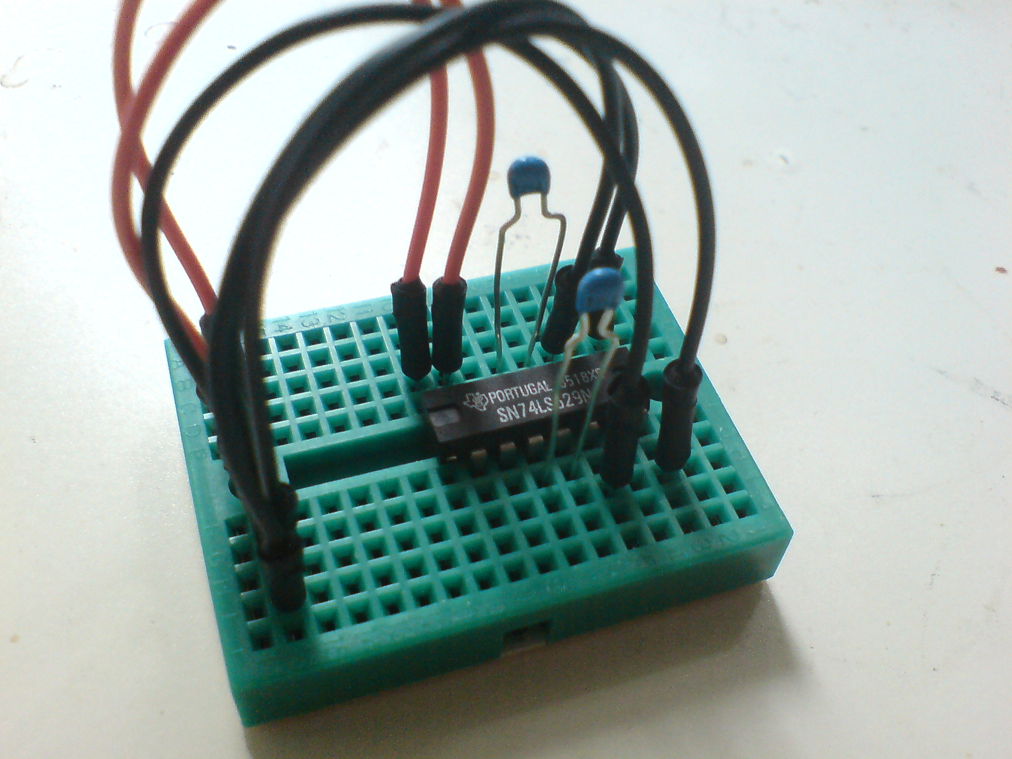
Adding capacitors (pins 12 to 13 and 4 to 5)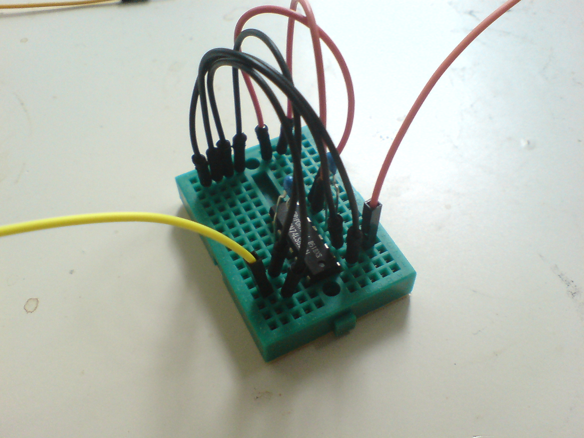
Male-to-female wires on outputs (pin 7 and 10)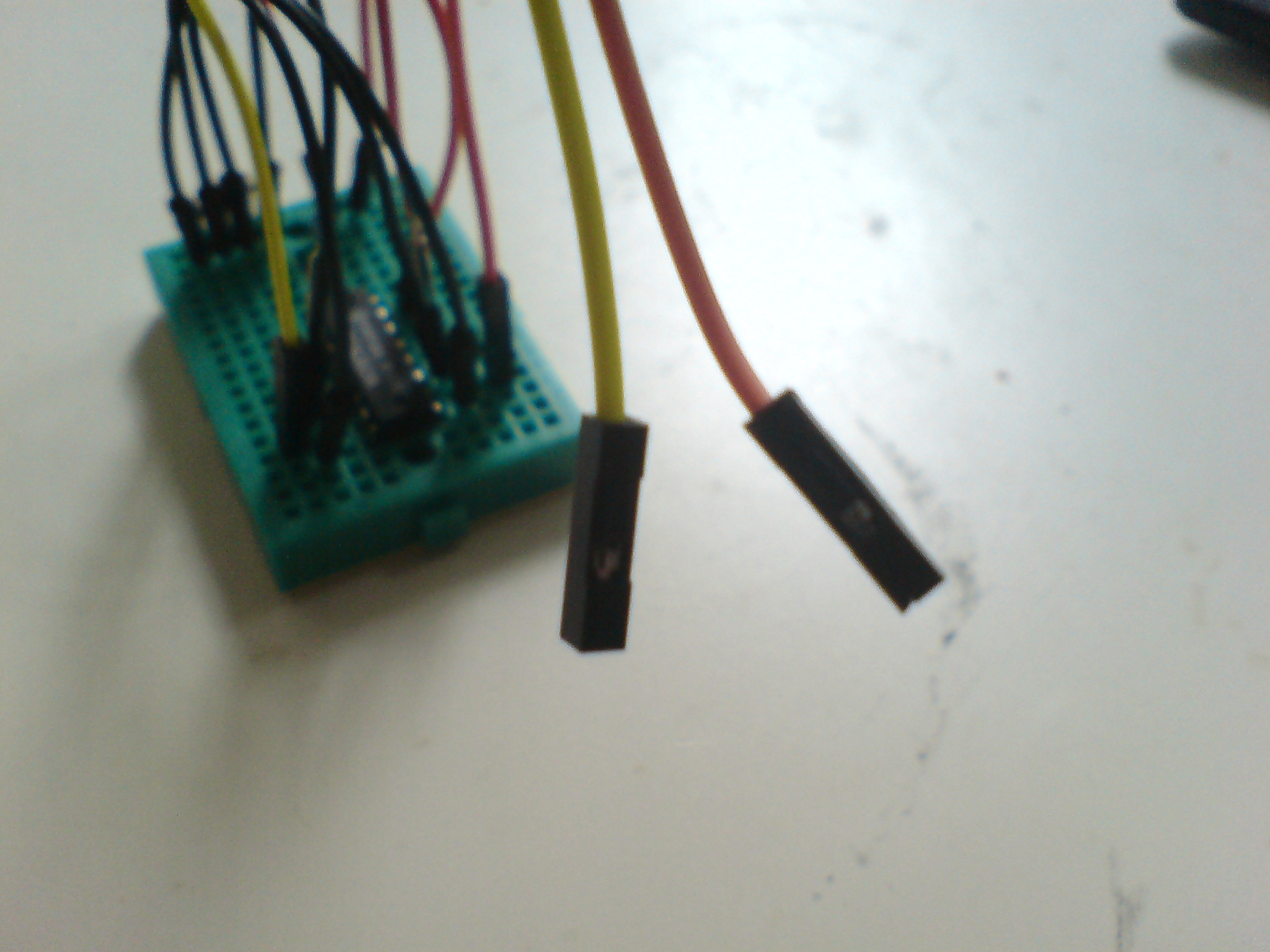
We'll connect the two female ends to the jack socket in a second
In the same way, we can connect the frequency and range inputs on pins 2 and 3 (for oscillator #1) and pins 1 and 14 (for oscillator #2) with male-to-male wires. The ends do not need to be connected to anything at this point. Also add one male-to-male wire to the row of power wires.
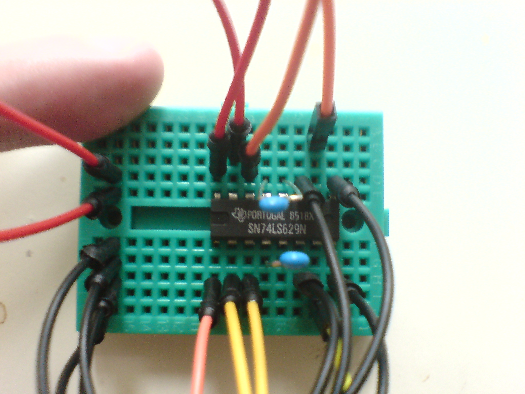
Wires to frequency and range inputs of each oscillator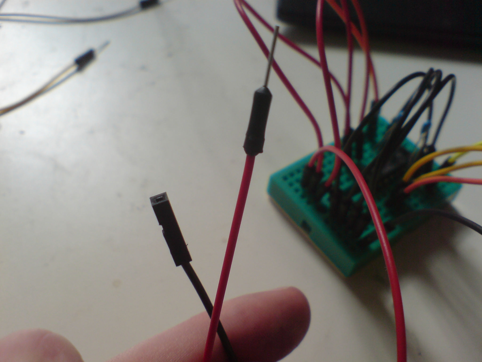
One more power (male) and ground (female) wires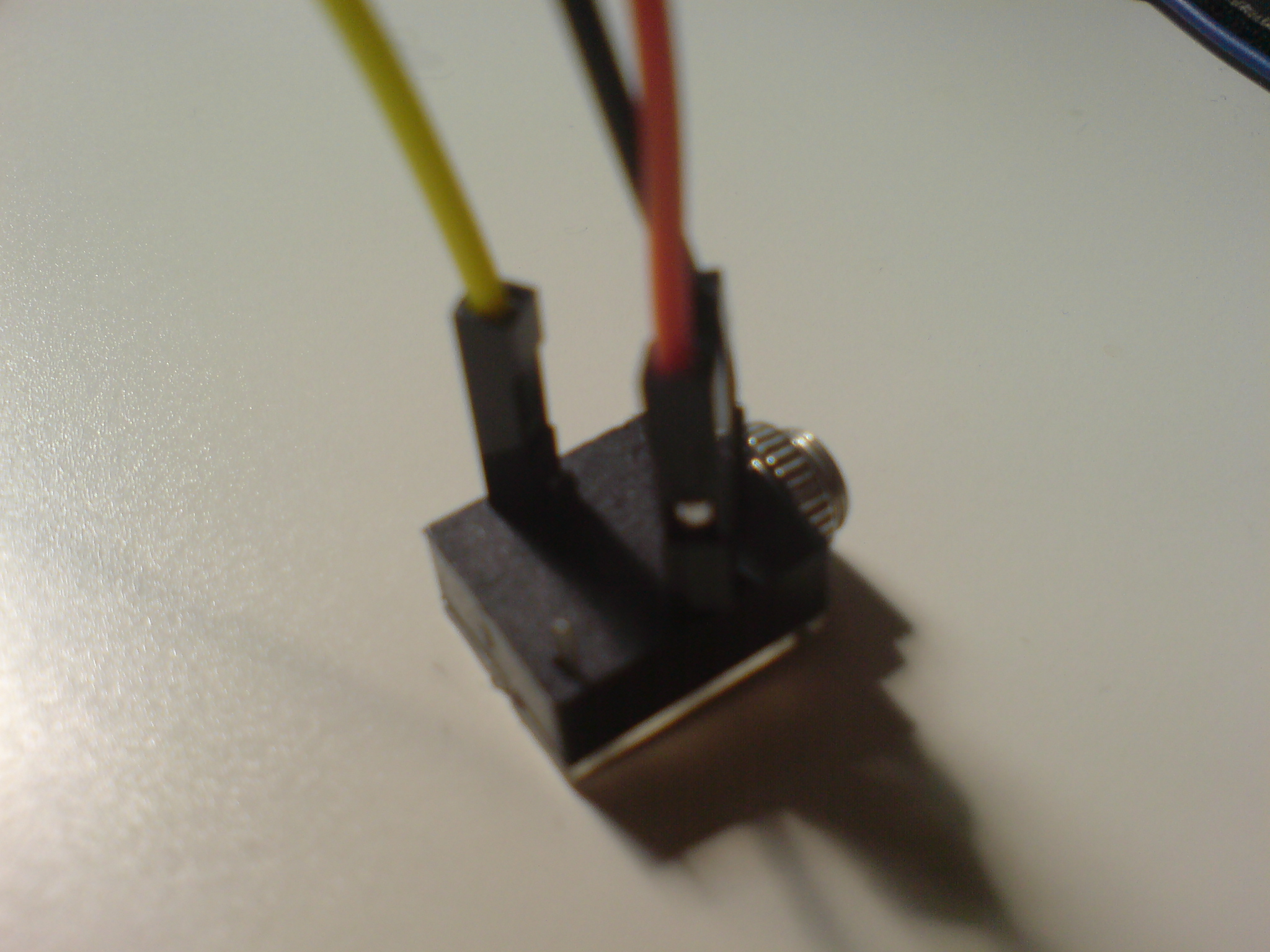
Connecting ground and the two outputs to jack socket
Finally, we connect the wires from the output pins, as well as one wire from ground to the jack socket. Connect the power and ground rows to your 5 volt power source and a set of stereo speakers to the jack socket (start at low volume!!), and you should hear a high-pitch noise in each speaker.
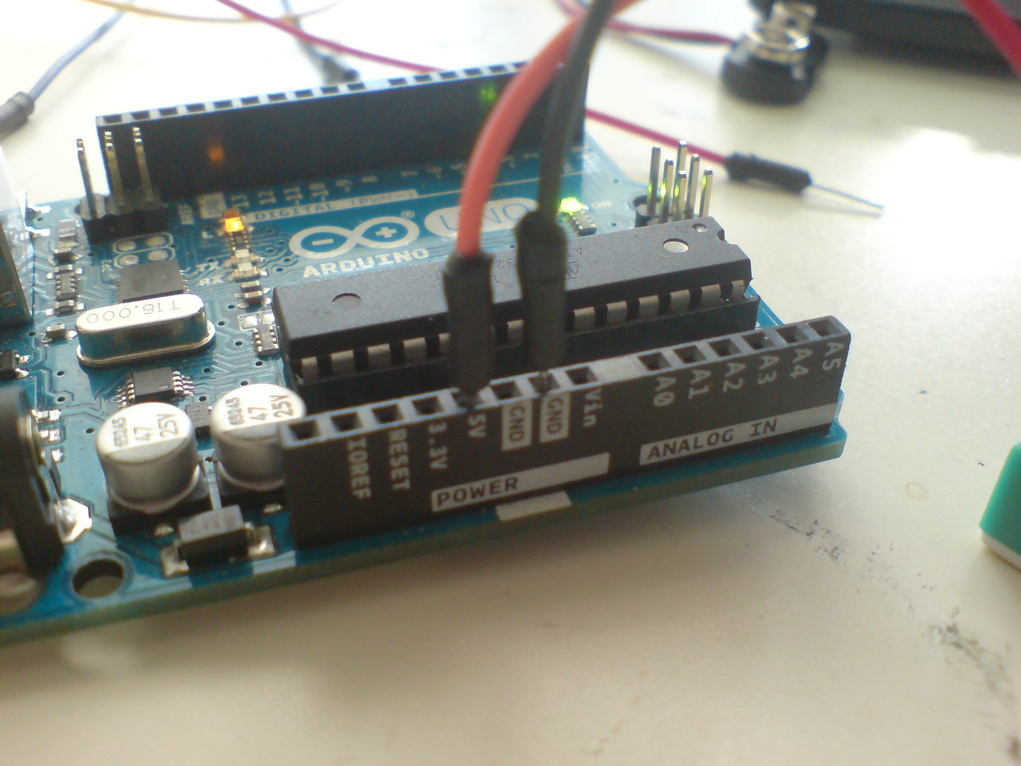
Connect to 5 volt power supply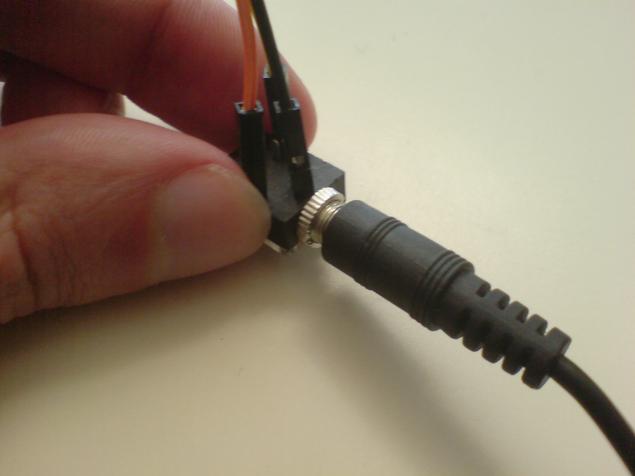
Connect to stereo speakers (start at low volume)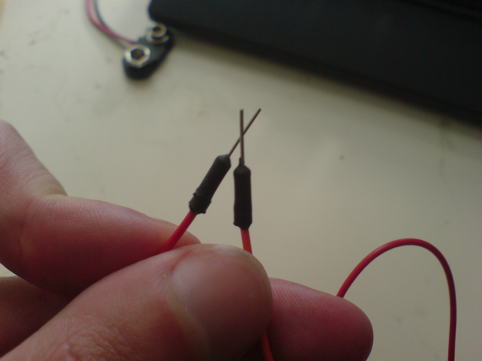
Connect power to each input pin to control pitch
If the circuit is working, you can use a wire with alligator clips to connect the power wire on either of the four loose ends that control the oscillators, and you should hear the pitch modulate. If you provide resistance between the power and the input wire (e.g. by touching one wire with each hand, so that the current runs through your body and reacts to it's resistance) the pitch changes.
The KVS Oscillator aka Kazz Noizer is an easy application of the SN74LS629N. The LS629 contains two oscillators running on the same power source but with seperate input for frequency and range control. If you look in the datasheet you can see the different functions of each pin.
Pin information from datasheet
Circuit diagram
Materials needed
Chip in breadboard
Connecting to power
Connecting to ground
Then we put one male-to-female wire to each of the output pins (pin 7 for oscillator #1 and pin 10 for oscillator #2). We'll connect the two female ends to the jack socket in a second. I've chosen a yellow wire for oscillator #1 and an orange wire for oscillator #2 to keep track of the oscillators, but this is not essential.
Adding capacitors (pins 12 to 13 and 4 to 5)
Male-to-female wires on outputs (pin 7 and 10)
We'll connect the two female ends to the jack socket in a second
Wires to frequency and range inputs of each oscillator
One more power (male) and ground (female) wires
Connecting ground and the two outputs to jack socket
Connect to 5 volt power supply
Connect to stereo speakers (start at low volume)
Connect power to each input pin to control pitch
Step 2: Connecting with Kasper Video System
Connecting this circuit to the Kasper Video System is easy. Instead of (or along side) connecting the output pins to the jack socket, you can connect the output into one or more color pins on the KVS Splicer and see the result. Just connect the h sync, v sync and ground to the output of a KVS splitter, and connect the KVS Oscillator.
As you modulate the frequency of the wave, the screen will produce horizontal lines scrolling at different speed, with variable spacing and size.
As you modulate the frequency of the wave, the screen will produce horizontal lines scrolling at different speed, with variable spacing and size.
Step 3: Making it portable (optional)
Especially if you plan on using the noizer, I recommend that you make it portable by making a battery-driven power supply. This is easily done with a positive voltage regulator (5 volt), a battery clips, a 9 volt battery and (optionally) a on-off button.
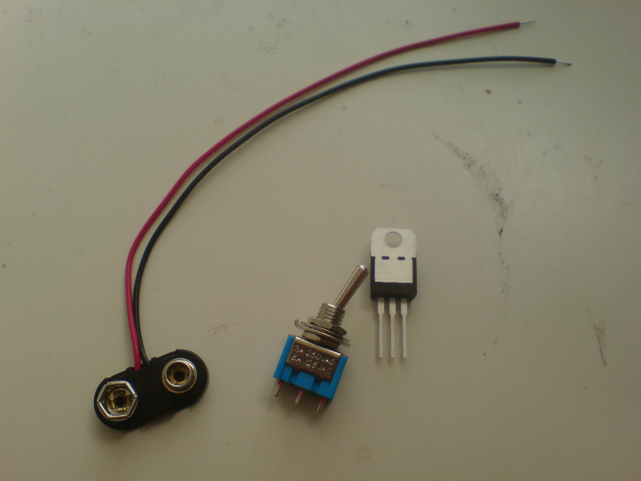
Materials needed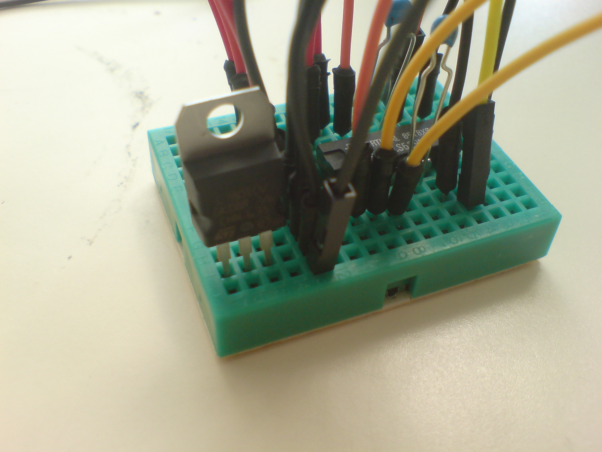
Attach regulator to breadboard - metal site away from yourself
The positive voltage regulator is needed to transform the 9 volt battery to 5 volt suitable for the chip. Attach the regulator on your breadboard with the metal site away from you. Now, the middle pin is for the ground wire from the battery clip and the pin on your left is for the power wire of the battery clip.
To use the voltage from the regulator, you attach the power connection to the right pin of the regulator, which provides the 5 volt power source. For ground just use the middle pin.
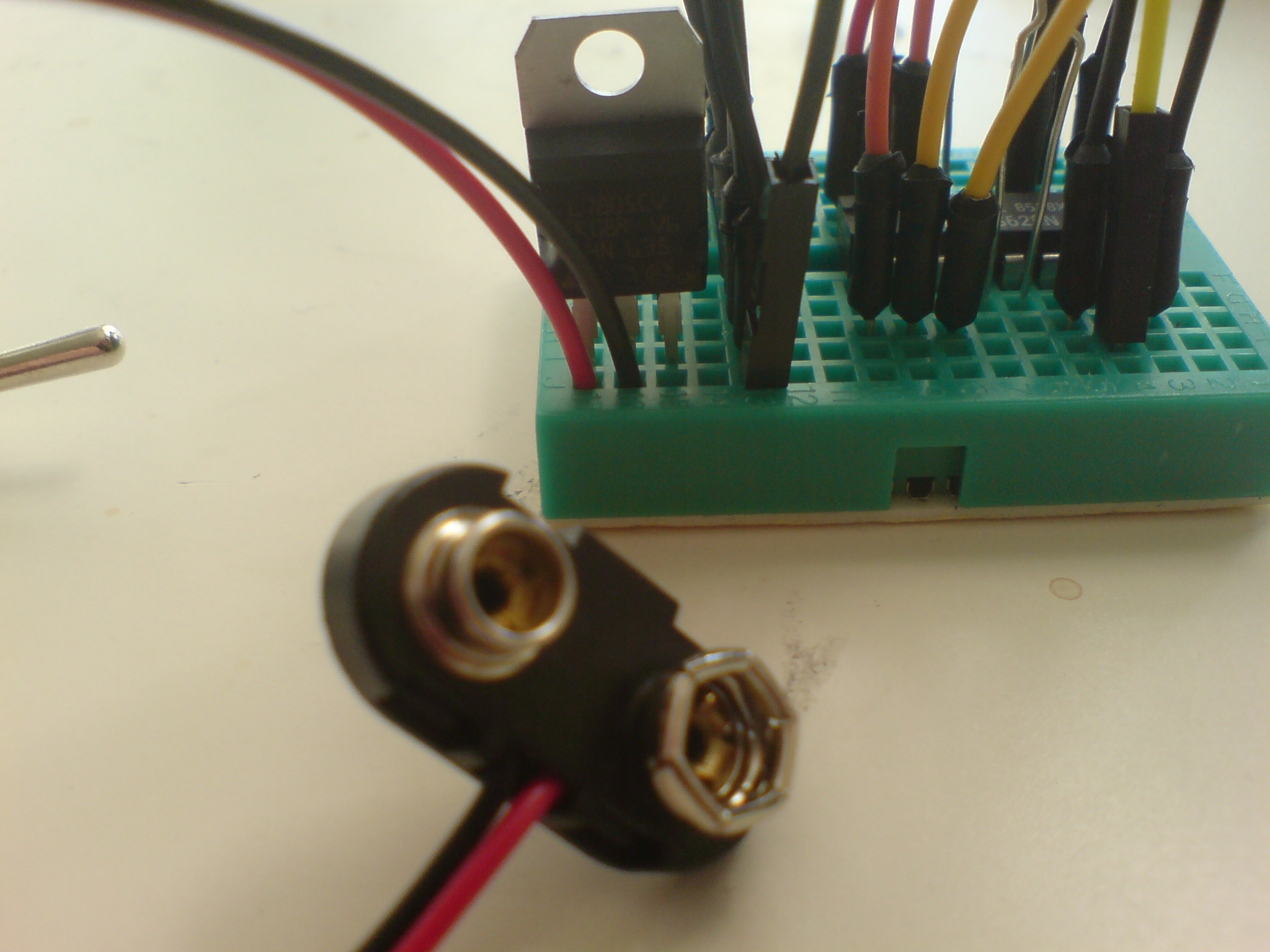
Connect battery clips to regulator (left pin is power, middle pin is ground)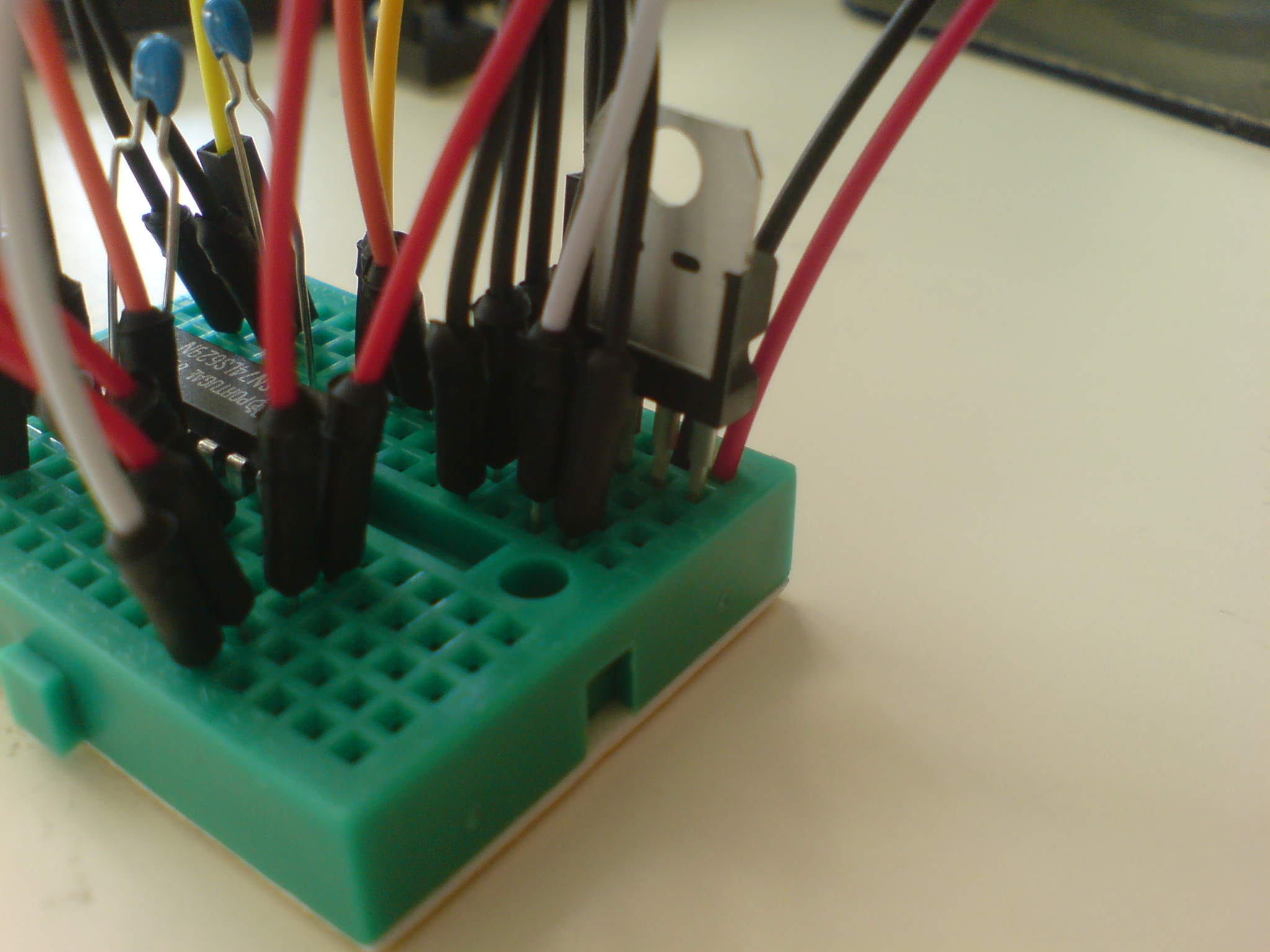
Connect regulator to circuit (right pin is 5 volt, middle is ground)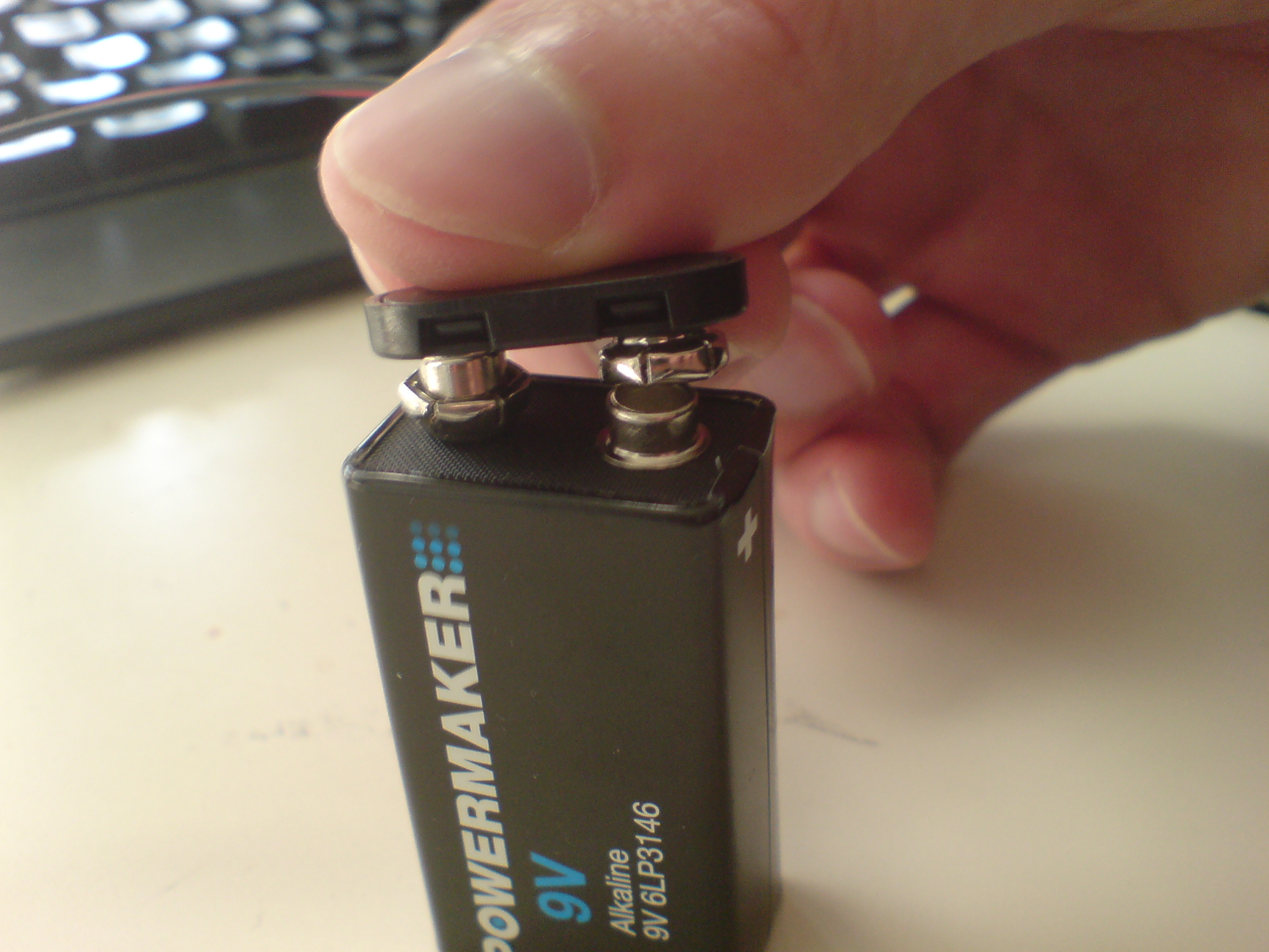
Connect battery
Attach the battery to the clips and hear if it works.
Whenever the battery is in the clip, the chip is running - even if your jack socket is not connected to a speaker. This means that you should always remember to remove the battery when the device is not in use, in order to save power. Alternatively, you can add a on/off button on the power wire from the battery clip, ie. before it reaches the voltage regulator. This way you can turn the device on and off without removing the battery.
Finally, you can find a box, make holes in it and mount the wires, sockets and button to it. I've made one using a plastic jar where I've made a hole for the jack socket in the middle. Then I've made three small holes on each side for the frequency and range input for each oscillator as well as one for the output.
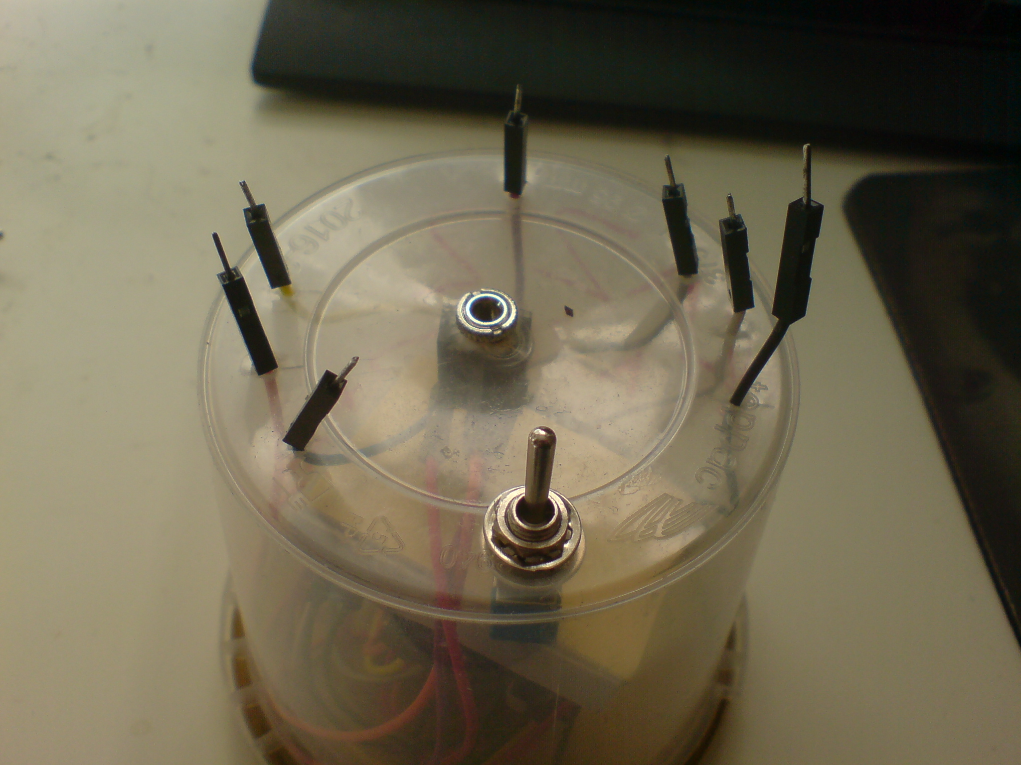
Mounted in plastic jar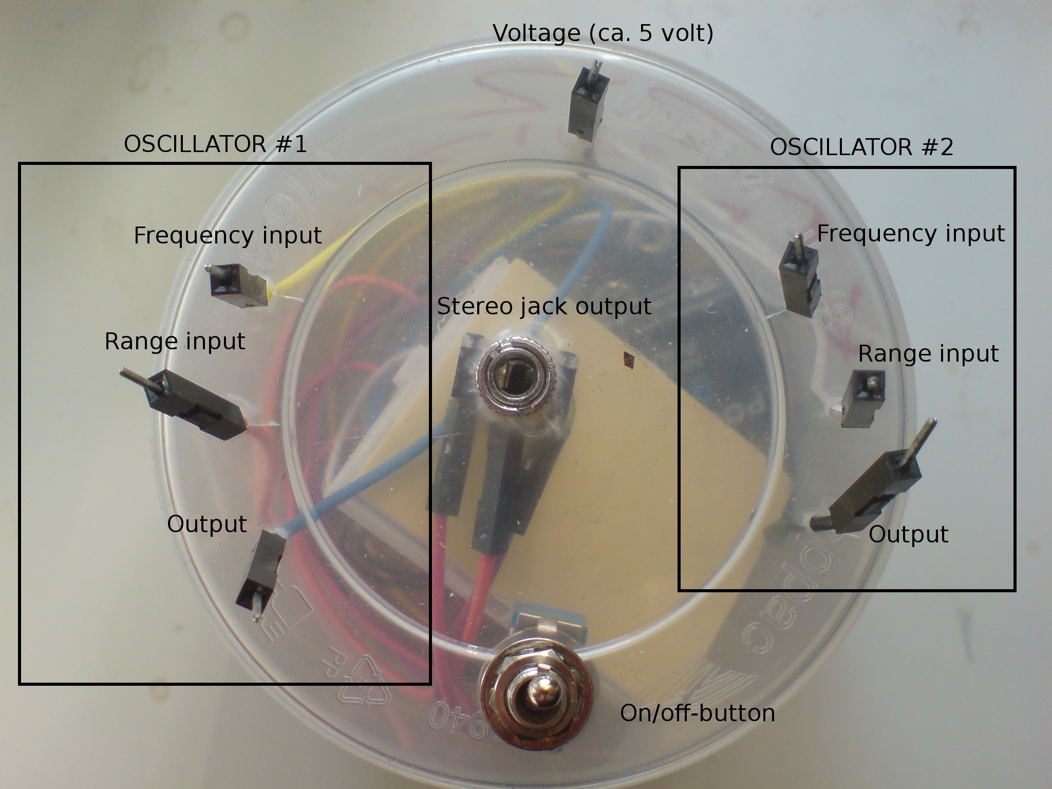
Diagram of pins and connections
With the outputs, you can connect the output of the oscillator to one of it's own inputs and make feedback, or even connect both outputs of each oscillator to the input of the other to make even more complex feedback patterns.
In the middle I've made a small hole for the jumper wire that brings power (directly from the regulator output) and the on/off button on the other site.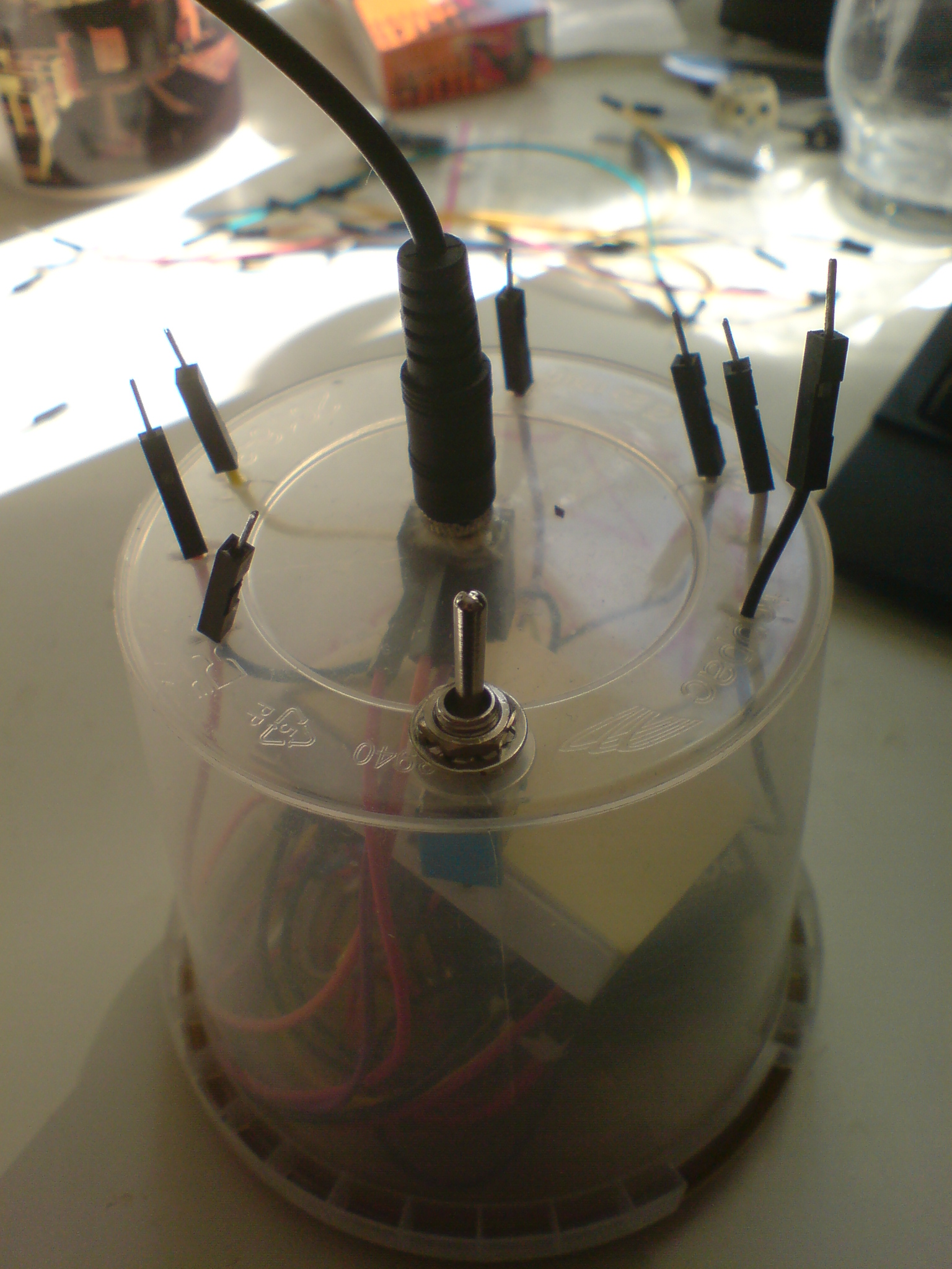
Plug stereo speakers in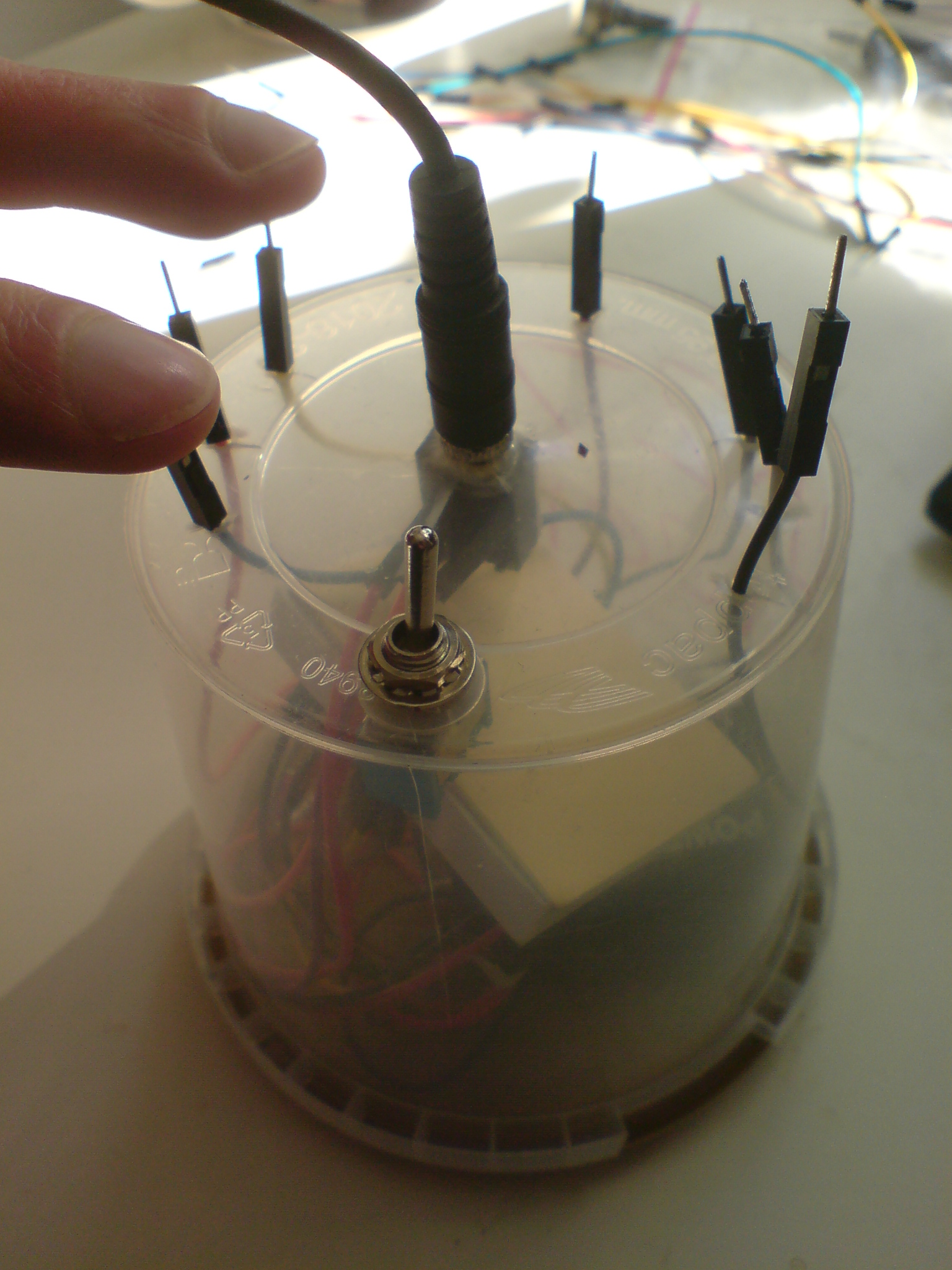
Output of oscillator controls it's own input (feedback)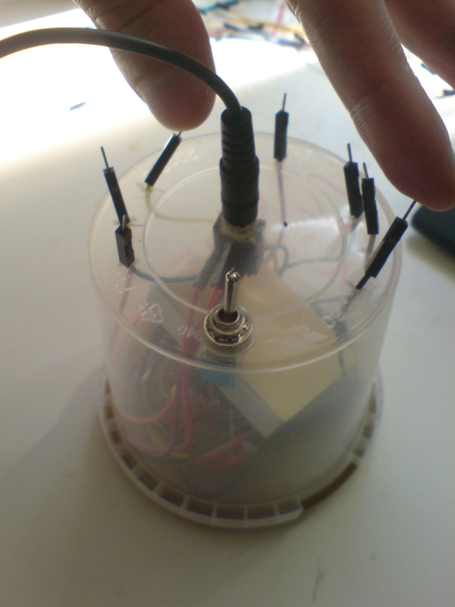
Output of one oscillator is the input of another (and so on...)
Materials needed
Attach regulator to breadboard - metal site away from yourself
To use the voltage from the regulator, you attach the power connection to the right pin of the regulator, which provides the 5 volt power source. For ground just use the middle pin.
Connect battery clips to regulator (left pin is power, middle pin is ground)
Connect regulator to circuit (right pin is 5 volt, middle is ground)
Connect battery
Whenever the battery is in the clip, the chip is running - even if your jack socket is not connected to a speaker. This means that you should always remember to remove the battery when the device is not in use, in order to save power. Alternatively, you can add a on/off button on the power wire from the battery clip, ie. before it reaches the voltage regulator. This way you can turn the device on and off without removing the battery.
Finally, you can find a box, make holes in it and mount the wires, sockets and button to it. I've made one using a plastic jar where I've made a hole for the jack socket in the middle. Then I've made three small holes on each side for the frequency and range input for each oscillator as well as one for the output.
Mounted in plastic jar
Diagram of pins and connections
In the middle I've made a small hole for the jumper wire that brings power (directly from the regulator output) and the on/off button on the other site.
Plug stereo speakers in
Output of oscillator controls it's own input (feedback)
Output of one oscillator is the input of another (and so on...)
Congratulations
Now go out and make noise and lines!!
Filmmaskiner.dk by Kasper Lauritzen is licensed under a Creative Commons Attribution-NonCommercial-ShareAlike 4.0 International License.